


120
Epsilon EP-I Indexing Drive and FM-2 Indexing Module Reference Manual
1. Assume the motor terminals of the non-Control-Techniques motor are designated A, B and C. If they are not marked,
name the terminals randomly. The next steps will determine their working designations.
2. You can select any of the three motor terminals and call it R. In this procedure we will choose terminal A.
The rotation of the motor will generate dangerous voltages and currents on the motor phase leads. Make sure the wires
and connections are properly insulated.
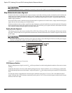
3. Connect the scope to read VCA and VBA. VCA and VBA are measured by putting the probe ground clips on A and the
scope probes on C and B.
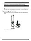
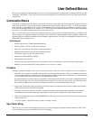
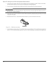
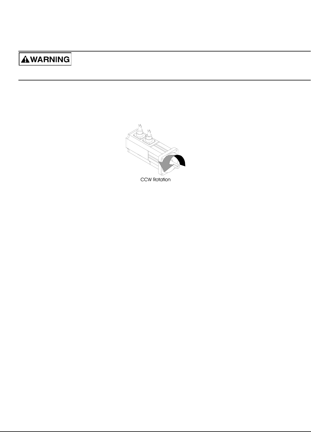
4. Rotate the motor CCW (i.e., rotate the shaft counter-clockwise as you face the shaft end of the motor).
Figure 105: CCW Rotation of the Motor
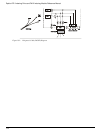
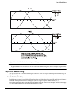
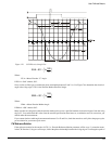
5. Look at the phase-to-phase voltages VCA and VBA. There are two possibilities. If VCA leads VBA, then assign B to S
and C to T. If VCA leads VBA, then assign B to T and C to S. These relationships are summarized in the figure below.