


125
User Defined Motors
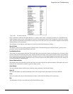
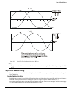
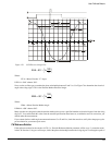
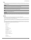
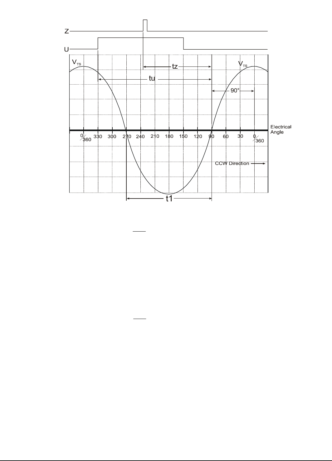
Figure 112: CCW Electrical Angle Plot
Where:
EUA = Motor Encoder “U” Angle
If EUA is >360° subtract 360°.
Next, use the oscilloscope to examine the phase relationship between Z and V
TS
. Use Figure 76 to determine the electrical
angle at the rising edge Z. This is the Encoder Marker Electrical Angle.
Where:
EMA = Motor Encoder Marker Angle
If EMA is >360° subtract 360°.
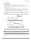
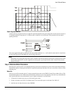
Many encoders are designed so that the encoder marker pulse occurs a specified number of electrical degrees from the rising
edge of U. You could obtain this value from the encoder specification sheet however, to minimize errors in conversion, you
should make this measurement.
If you cannot obtain a stable angle measurement between U or Z and V
TS
, check the encoder to verify it has the proper cycles
per revolution for your motors pole count.
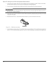
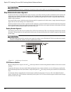
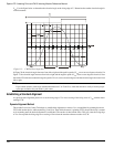
CW Reference Rotation
If the reference motion for the encoder is CW (i.e., Encoder Reference Motion parameter will be set to 1), rotate the motor
in the CW direction. Using an oscilloscope, look at the phase relationship between the rising edge of U and negative peak of
⎟
⎠
⎞
⎜
⎝
⎛
+°=
t1
180
tu 90 EUA
⎟
⎠
⎞
⎜
⎝
⎛
+°=
t1
180
tz 90 EMA