


103
Tuning Procedures
Tuning Parameters
Inertia Ratio
Inertia Ratio specifies the load to motor inertia ratio and has a range of 0.0 to 50.0. A value of 1.0 specifies that load inertia
equals the motor inertia (1:1 load to motor inertia). The drives can control up to a 10:1 inertia mismatch with the default
Inertia Ratio value of 0.0. Inertial mismatches of over 50:1 are possible if response is reduced.
The Inertia Ratio value is used to set the internal gains in the velocity and position loops, including feedforward compensation
if enabled.
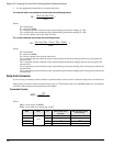
To calculate the Inertia Ratio value, divide the load inertia reflected to the motor by the motor inertia of the motor. Include
the motor brake as a load where applicable. The resulting value should be entered as the Inertia Ratio parameter.
Where:
IR = Inertia Ratio
RLI = Reflected Load Inertia (lb-in-sec
2
)
MI = Motor Inertia (lb-in- sec
2
)
If the exact inertia is unknown, a conservative approximate value should be used. If you enter an inertia value higher than the
actual inertia, the resultant motor response will tend to be more oscillatory.
If you enter an inertia value lower than the actual inertia, but is between 10 and 90 percent of the actual, the drive will tend
to be more sluggish than optimum but will usually operate satisfactorily. If the value you enter is less than 10 percent of the
actual inertia, the drive will have a low frequency oscillation at speed.
There are three guidelines for defining the inertia ratio:
1. In most applications the default value of 0 (zero) will be used.
2. If the inertia of the machines varies or there is uncertainty in the estimate, use the lowest value for inertia.
3. The machine system bandwidth is reduced if the inertia estimate is low. Consequently a low inertia estimate can
sometimes add a level of robustness.
Friction
In the drive, this is a viscous friction parameter, characterized in terms of the rate of friction increase per 100 motor RPM.
The range is 0.00 to 100.00 in units of percent continuous torque of the specified motor/drive combination. The Friction value
can either be estimated or measured. For most servo drives viscous friction is 0.
If estimated, always use a conservative (less than or equal to actual) estimate. If the friction is completely unknown, a value
of zero should be used. A typical value used here would be less than one percent.
If the value entered is higher than the actual, system oscillation is likely. If the value entered is lower than the actual a more
sluggish response is likely but generally results in good operation.
Response
The Response adjusts the velocity loop bandwidth with a range of 1 to 500 Hz. In general, it affects how quickly the drive
will respond to commands, load disturbances and velocity corrections.
Note
The drive’s position velocity loop is designed to be a second order system with a gain of one, a natural frequency specified
in the Response scroll box, and a damping factor of 0.8. If the drive’s bandwidth is defined to be the -3dB point of the
response, the idealized bandwidth of the system is approximately 2.2 times greater than the natural frequency.
For example: When the Response is set to 50, the idealized bandwidth is 110 Hz.
MI
RLI
R I =