


9
Setting Up Parameters
nLines = Total number of Encoder Lines
n = Motor Encoder Lines per Rev Coefficient
x = Motor Encoder Exponent
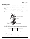
The total number of encoder lines is used both for commutation and for position/velocity control. To properly commutate the
motor, the drive must know the electrical angle (the angle between the motor magnetic field and stator coils).
Encoder Lines/Rev Exponent
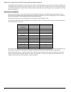
Specifies a coefficient for determining the number of encoder lines per mechanical revolution. The supported values are 1 to
16383. The equation for determining the total number of encoder lines per revolutions is:
nLines = n*10x
where:
nLines = Total number of Encoder Lines
n = Motor Encoder Lines per Rev Coefficient
x = Motor Encoder Exponent
The total number of encoder lines is used both for commutation and for position/velocity control. To properly commutate the
motor, the drive must know the electrical angle (the angle between the motor magnetic field and stator coils).
Encoder Marker Angle
Specifies the electrical angle at which the marker (Z) pulse occurs with reference to V
TS
when the motor is spun in the encoder
reference direction. At power-up the drive obtains an initial estimate of the electrical angle from the status of the U, V and W
commutation tracks. This estimate can be off by as much as 30 °.
When the drive receives the marker pulse, the drive will, within one second, gradually shift the commutation to the more
accurate electrical angle specified by this parameter. The system will then operate more efficiently.
Encoder U-track Angle
Specifies the electrical angle at which the rising edge of the U commutation track will occur with reference to VTS when the
motor is spun in the encoder reference direction.
At power-up the drive looks at the status of the U, V and W commutation tracks and, using this parameter, obtains a crude (±
30 °) estimate of the electrical angle.
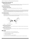
Encoder Reference Motion
Specifies the direction of motion assumed in phase plots of the encoder’s quadrature and summation signals. The supported
values are CW(1) and CCW(0). Your encoder may have the same phase plot but is generated from a different direction of
rotation. This parameter affects the way the drive interprets the quadrature and commutation signals.
Encoder Type
The supported values for this parameter are 1 and 0. If set to a 1 the drive uses the Encoder Marker angle as well as the
Encoder U Angle for commutation. If this parameter is set to a 0, the drive uses only the Encoder U Angle.
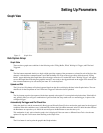
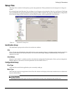
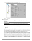
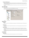
Values from Drive Column
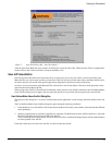
The Values from Drive column is a group of parameters that are constantly being read from the drive. The theory of operation
is that the user will often perform an Auto-Tune function that reads/measures/calculates data. The results of those
measurements are read from the drive and displayed in the Values from Drive column. Once they are displayed in PowerTools
Pro (in the Values From Drive column) the user can apply those values to the Motor Parameters column by clicking on the
Apply to Config. button, in the middle of the Motor view (this button looks like a series of arrows pointing from the Values
from Drive column towards the Motor Parameters column).
The values in the Values from Drive column are not saved as part of the configuration file. To save these values, the user
must use the “Apply to Config” button to save them.
This column is only functional when online with the device. When offline, the values in the Values from Drive column will
all read zero.
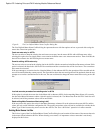
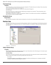
Apply to Config. Button
When the user runs the Auto-Tune feature PowerTools Pro reads the results of the Auto-Tune and displays them in the Values
from Drive column of the Motor view. After the Auto-Tune, the measured values are only saved in the Drive NVM, and not