


134
Epsilon EP-I Indexing Drive and FM-2 Indexing Module Reference Manual
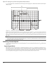
To confirm this repeat Steps 7-9 several times with different motor shaft starting locations. If the absolute value of the
parameter is greater than 40, there is either a problem with the phasing of U, V and W or an inconsistency in the encoder
alignment parameters.
Torque Test
The purpose of this test is to enable the drive in Torque mode and verify that a positive command produces CW torque.
1. Use PowerTools Pro to select Torque mode and set Full Scale Torque to 5 percent. Then click the Update button to
download the changes to the drive.
With Full Scale Torque set to 5 percent, a maximum analog command of 10 volts will generate 5 percent of continuous
torque in the motor which should be enough to spin the motor but not to damage it.
2. Move to the Analog view and find the “Analog Input” parameter.
3. Using your simulator adjust the analog command until the value of this parameter is approximately 0 volts.
4. Enable the drive. It should not move. If the drive faults at this point you most likely have a wiring problem (see “Step 1:
Motor Wiring”).
5. Gradually increase the analog command voltage. The motor should start moving with a voltage level somewhere between
2 and 5 volts. Verify that the direction of motion is CW.
6. If there is CCW or no motion, there is a problem with encoder alignment parameters. If the motor moves 30 to 90 ° and
then stops, there could be one of several problems:
• The number of Motor Poles has been specified incorrectly.
• The Encoder Lines Per Revolution parameter has been specified incorrectly
• The motor terminals have been mis-identified (see “Step 1: Motor Wiring”).
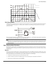
Commutation Accuracy Test
This test will determine how accurately the encoder Z channel has been specified. It requires that the motor be connected and
ready to run but it will be spun by the drill motor while in Torque mode with a zero torque command.
1. Disable the drive.
2. Set the Torque Limit to 0.
3. Make the Torque Limit input function always active.
4. Enable the drive.
5. Select “View Motor Parameters” from the Tools menu so you can monitor the Commutation Voltage.
6. Spin the motor clockwise 500 to 1000 RPM, then counter-clockwise at the same speed.
The Commutation Voltage should be <10 percent. If the Commutation Voltage is higher than 10 percent, the Motor
Encoder Marker Angle was incorrectly specified and should be re-tested.
7. Reset the Torque Limit and the Torque Limit Enable input function to their previous settings.
Velocity Test
1. Disable the drive.
2. Select Velocity Analog mode and set “Full Scale Velocity” parameter to 12 RPM.
3. Use the simulator to adjust the analog command voltage to 5 volts.
4. Enable the drive. Find the “Velocity Command Analog” parameter on the Status view. Adjust the analog command until
this parameter reads exactly 6 RPM. The motor should be moving at 6 RPM. If the system got through the Torque test,
the motor should not run-away at this point. If it does, go back and repeat the Torque test.