


126
Epsilon EP-I Indexing Drive and FM-2 Indexing Module Reference Manual
V
TS
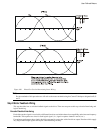
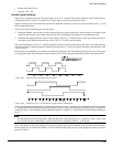
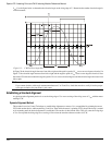
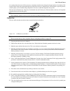
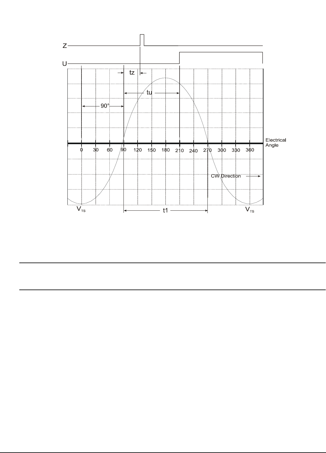
. Use the figure below to determine the electrical angle at the rising edge of U. Determine the marker electrical angle in
a similar manner.
Figure 113: CW Electrical Angle Plot
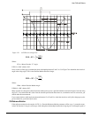
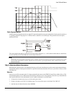
In Figure 76 the electrical angle decreases from left to right and the positive peak of V
TS
occurs at zero degrees electrical. In
Figure 77 the electrical angle increases from left to right and the negative peak of V
TS
occurs at zero degrees electrical. Note
that with a CW reference rotation the negative peak of V
TS
is at zero electrical degrees and the electrical angle decreases from
left to right.
Note
If you cannot obtain a stable angle measurement between U or Z and V
TS
, check the encoder to verify it has the proper
cycles per revolution for your motor’s pole count.
Establishing a Standard Alignment
A typical encoder alignment practice is to set the rising edge of U to zero crossing of the rising wave of V
SR
with the motor
rotating CCW.
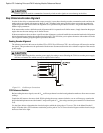
Dynamic Alignment Method
This method is used at Control Techniques to establish the alignment on motors. It is accomplished by spinning the motor
CCW with another device while monitoring U and V
SR
. Then while the motor is spinning CCW, the encoder body is rotated
on its mounting until the desired alignment is established. The encoder is then locked down. This will cause the rising edge
of V to line up with the rising edge zero crossing of V
RT
when the encoder reference rotation is CCW.