


119
User Defined Motors
Drives can be configured to operate with brushless DC (synchronous permanent magnet) motors not manufactured by Control
Techniques. This feature is very useful for users who are retrofitting drives on existing systems or who have special motor
requirements.
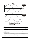
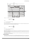
Commutation Basics
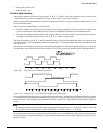
To properly commutate the motor, the drive must know the electrical angle (the angle between the motor magnetic field and
stator coils; R, S and T). At power-up, the drive determines the starting electrical angle from the U, V and W commutation
tracks. After this is determined, the U, V and W commutation tracks are ignored and the commutation is entirely based on
the A and B incremental channels. The number of U, V and W cycles must match the number of poles in the motor but they
do not have to be aligned with the motor poles in any particular way.
The U, V and W tracks have a fairly coarse resolution, therefore, on power-up, the commutation accuracy is limited to ±30
electrical degrees from optimum. When the Z channel is seen by the drive, the commutation angle is gradually shifted to the
optimum position as defined by the Motor Encoder Marker Angle parameter. This shift is accomplished in about one second
whether the motor is rotating or not.
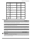
Tools Required:
• Oscilloscope dual trace 5 Mhz bandwidth minimum.
• AC/DC voltmeter, 20 Vdc and 200 VAC minimum.
• Drill motor (reversible) or some means of spinning the motor.
• Coupling method between the drill motor and the test motor.
• 5 Vdc power supply to power the motor encoder.
• Motor power cable (CMDS or CMMS).
• Motor feedback cable (CFCO).
• Terminal strip (18 position suggested) to conveniently connect the motor power and encoder wires during testing.
• Method to securely hold the motor during operation (a vise or large C-clamp).
Procedure
The steps required to assemble a servo system consisting of a drive, and a non-Control-Techniques motor are listed below:
1. Determine if your motor is compatible with the drive by verifying its characteristics. There are a number of restrictions
such as encoder line density and motor pole count that must be considered. Most of these parameters are commonly found
on a motor data sheet and some may have to be determined by testing.
It is important that the encoder used have a repeatable Z channel angle with reference to one of the commutation channels.
This is especially the case if you will be using the same encoder on several motors and you wish to use the same setup
file on them all. Otherwise you will need to generate a motor file for each individual motor/encoder.
2. Design and assemble the cabling and interface circuitry required to connect the motor and drive. Motor and feedback
cables must be properly shielded and grounded.
3. Determine the encoder alignment. In order to commutate a motor correctly the angular relationship of the encoder
commutation tracks and the marker pulse with respect to the R, S and T windings in the stator must be known.
4. Enter the motor/encoder data into the MOTOR.DDF file. This data is then read by the PowerTools Pro software when
setting up the drive.
5. Test your system to verify that the servo system is working correctly.
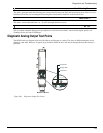
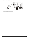
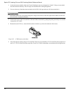
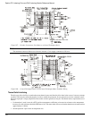
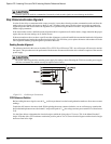
Step 1:Motor Wiring
The first step is to wire the motor terminals to the drive. Control Techniques designates the motor terminals as R, S and T.
Use the following procedure to establish the R, S and T mapping:
Epsilon EP-I Indexing Drive and FM-2 Indexing Module
Reference Manual