


75
Operational Overview
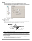
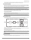
Signal common connected to Drive Logic 0V (Sync Encoder Common 0V)
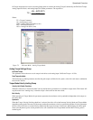
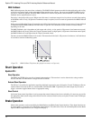
Epsilon EP-I Wiring Example:
Note
Actual motor rotation direction will depend on pulse ratio polarity and setting of the Positive Direction bit.
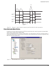
Pulse Mode Parameters
The Pulse Input Posn parameter shows the total pulse count received by the drive since the last power-up.
The Pulse Input Posn, Position Command, Encoder Feedback and Position Feedback are initialized to zero on power-up. Only
Position Feedback Encoder can be preloaded serially with a value after power-up.
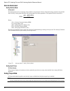
Pulse Mode Ratio Setup Group
Ratio
The Ratio parameter includes a numerator that represents motor revolutions, and a denominator that represents master pulses.
The Pulse Mode Ratio Revolutions is allowed to be negative which reverses all Pulse mode motion.
Pulse Mode Acceleration Group
Max. Acceleration
Sometimes when pulse mode is enabled, the Master will already be traveling at a velocity. By default the drive will attempt
to ramp up to this velocity in one processor control loop. In most applications this very fast accel is not desirable. The
maximum acceleration parameter displays a maximum ramp that the follower will use to ramp up to the specified pulse ratio.
Once the follower is at the Master velocity, this accel parameter is disabled and the follower will follow pulse for pulse
depending on the specified ratio.
Pulse Mode Velocity Group
Enable Distance Recovery Check box
This check box when selected, activates the Distance Recovery feature of the drive. If a master is traveling at a velocity when
pulse mode is initiated the follower will travel up to the specified ratio using an acceleration as specified by the user. If using
the accel causes the follower to lose any pulses, these pulses will be saved into the Recovery Distance parameter and will be
added onto the followers profile after it obtains the specified ratio.
Max Recovery Velocity
This parameter sets the maximum velocity that the motor may obtain as it corrects for pulses lost during the accel portion of
pulse mode.
Enable Velocity Filter Check box
The Enable Velocity Filter check box is used to turn on or turn off the Input Pulse Velocity Filter. When the Enable check
box is selected, the filter is active and the user may select the bandwidth desired to filter above. If clear, the filter is not used.
Filter Bandwidth
This parameter represents the bandwidth in hertz of the input pulses velocity filter. This filter must be enabled in order for it
to function. The valid range of this parameter is 0 to 1200 hertz.
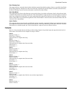
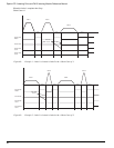
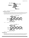
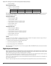
Pulse /: Commands motion on the falling edge (active edge).
Direction: Positive (+) motion when high (inactive) and Negative (-) motion when low (active).
Pulse CW /: Commands positive (+) motion on the falling edge (active edge) of a pulse.
Pulse CCW /: Commands negative (-) motion on the falling edge (active edge) of a pulse.
A and B: Encoder Quadrature signal interpretation. When B leads A Positive (+) motion
commands will be generated, When A leads B, negative (-) motion commands will be
generated.
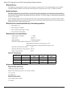
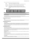
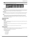
STI-SNCOA
terminal
Analog/Sync
Connector Pin #
Pulse-Direction
Signal
Pulse-Pulse
Signal
Pulse Quadrature
Signal
44Pulse /Pulse CW /A
12 12 Direction Pulse CCW / B