


113
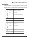
Diagnostics and Troubleshooting
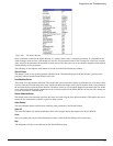
Max Following Error
This fault is generated when the following error exceeds the following error limit (default following error limit is 0.2 revs).
With PowerTools Pro you can change the Following Error Limit value or disable it on the Position view.
Travel Limit +/-
This fault is caused when either the + or - Travel Limit input function is active.
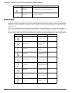
All “On”
This is a normal condition during power up of the drive. It will last for less than 1 second. If this display persists, call
Technical Service at Control Techniques.
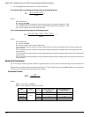
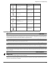
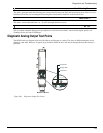
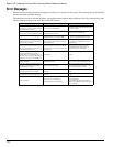
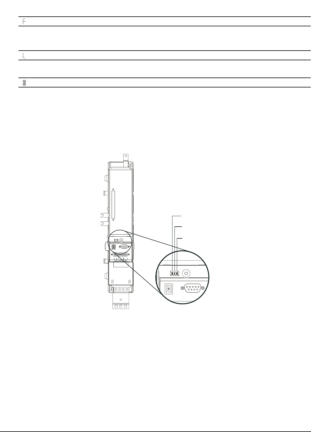
Diagnostic Analog Output Test Points
The DGNE cable was designed to be use with either an oscilloscope or a meter. The wires are different lengths to avoid
shorting to each other. However, if signals do get shorted to GND, the drive will not be damaged because the circuitry is
protected.
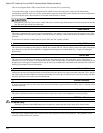
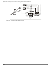
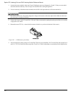
Figure 100: Diagnostic Output Test Points
Channel #2
Analog GND
Channel #1
MDS Drive Module
VDC
10-30
J6
+
OUTPUT
ENABLE
INPUT
3
-
DRIVE
21 14 32
RESET
VDC
10-30
J6
+
OUTPUT
ENABLE
INPUT
3
-
DRIVE
21 14 32
SERIAL
COMMAND
RESET
SERIAL
COMMAND
COMMAND
J5
SERIALSERIAL
J4