


122
Epsilon EP-I Indexing Drive and FM-2 Indexing Module Reference Manual
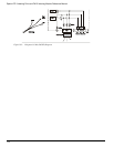
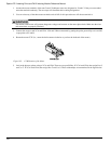
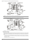
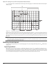
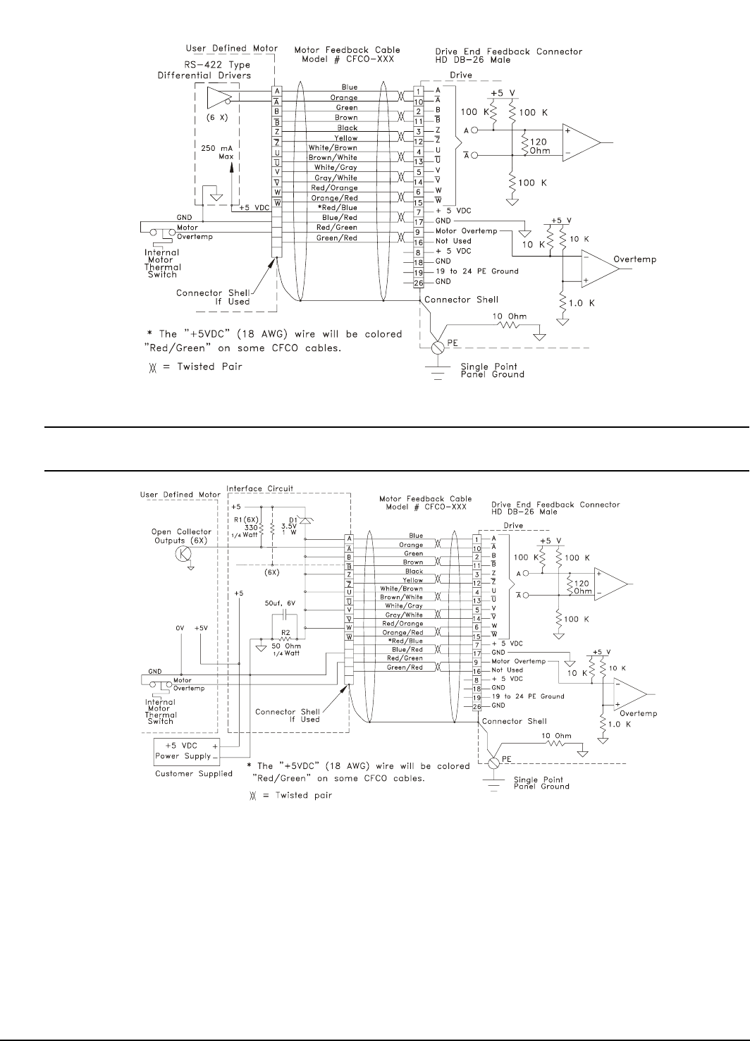
Figure 107: Encoder Connections, User Motor to a Control Techniques Drive
Note
The maximum current available out of the drive encoder +5 volt supply connection is 250 mA.
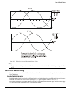
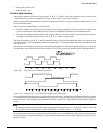
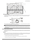
Figure 108: Control Techniques Drive to non-Control-Techniques Motor Feedback Wiring
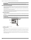
Thermal Switch Interfacing
The drive provides a facility to monitor the motor thermal sensor and shut the drive down in the event of a motor overtemp
condition. This must be connected properly in order to enable the protection. If your motor does not have a thermal sensor,
the sensor input pin is simply tampered to the encoder common ground (0 volt) pin. The thermal sensor requirements are as
follows:
• If a thermistor is used, it must be a PTC (positive temperature coefficient) or increases in resistance as the temperature
increases. Its cold resistance should be 500 ohms or less. The motor fault will occur when the thermistor resistance reaches
approximately 1.0 kohm.
• Switch Operation: open circuit on temperature rise