


127
User Defined Motors
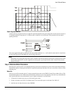
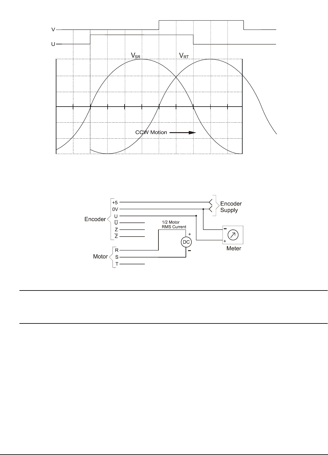
Static Alignment Method
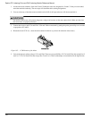
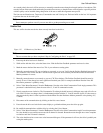
Another method to align the encoder is to apply DC current through the motor power phases R to S and rotate the encoder on
it’s mounting until the rising edge of U is detected with a voltmeter or an oscilloscope. This procedure does not require
spinning the motor.
The current applied through R to S should be the same polarity each time (i.e., + on R) and the current must be controlled to
no more than 50 percent of the RMS stall current rating of the motor.
Note
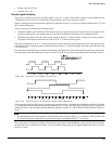
Verify that you are seeing the rising edge of the U channel in the encoder reference direction by twisting the motor shaft
CCW by hand while the DC current is applied and verifying that U goes high when the shaft is rotated in the encoder
reference direction.
Step 4: Determine Motor Parameters
Measuring the actual motor Ke is recommended because not all motor manufacturers use the same measurement techniques.
Normally the number of motor poles and the Ke is specified on the motor data sheet. If it not, or you wish to verify it, use the
following tests.
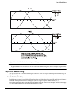
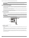
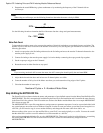
Motor Ke
In this test you will be measuring the AC voltage generated by the motor or the CEMF (Counter Electro-Motive Force). This
measurement requires an AC voltmeter that can accurately read sine waves of any frequency and some way to determine the
motor speed at the time of the measurement, such as a photo tachometer or an oscilloscope.
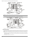
1. Connect the volt meter across any two of the motor power leads.
2. Set the volt meter to read VAC at its highest range. You can usually expect to read about 20 to 300 VAC.
3. Spin the motor in either direction at least 500 RPM.