


121
User Defined Motors
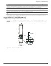
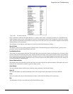
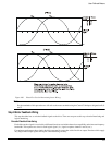
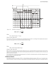
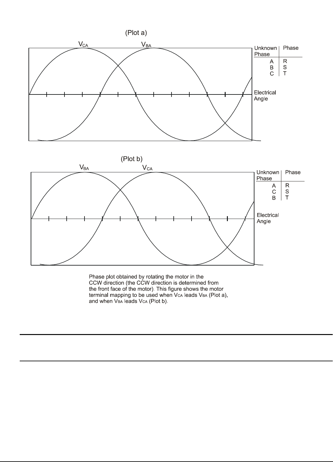
Figure 106: Phase Plot Used to Determining Stator Wiring
Note
For the remainder of this procedure we will refer to the motor terminals using the Control Techniques designations R, S
and T.
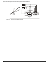
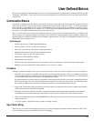
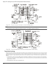
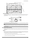
Step 2:Motor Feedback Wiring
This step describes how to wire the feedback signals to the drive. There are two parts to this step: electrical interfacing and
logical interfacing.
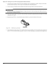
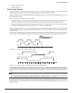
Encoder Electrical Interfacing
Each of the encoder signals is received by a differential receiver to minimize the noise susceptibility and to increase frequency
bandwidth. This requires two wires for each logical signal. (i.e., signal A requires channel A and A/, etc.).
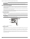
For optimum performance these signals should be generated by an encoder with a line driver output. Encoders which supply
only single ended output signals will require some interfacing circuitry.