


8
Epsilon EP-I Indexing Drive and FM-2 Indexing Module Reference Manual
Motor Parameters Column
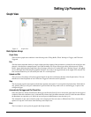
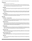
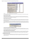
Motor Parameters column is a column of data displayed on the Motor view under the Setup view (See Figure 6). This column
of data contains the values for each of the motor data parameters. The values in this column are unavailable for edit if the
“Use Motor Data From .ddf File” check box is selected. This means that since the data is associated with the .ddf file, it cannot
be changed. The values in this column become available when the “Use Motor Data From .ddf File” check box is cleared.
The user can then change one or more of the parameter values because there no longer is a link to the data in the .ddf file.
If the user does edit motor parameter values on this view, those values are only stored within that particular configuration file.
In order to save the values to the .ddf file, the user must click the “Save .ddf Values” button on the right side of the view.
Below are the motor parameter with a brief description.
Motor Name
The motor name is limited to 12 characters and must begin with an alpha character (non-numeric character). This is the motor
name that will appear in the “Motor Type” list box above.
Peak Current
Specifies the peak current allowed by the motor. The motor manufacturer typically provides the peak current data.
If a system is “drive limited” (meaning that the motor can handle more current than the drive can deliver), the peak current
actually used by the system may be lower than the value specified here.
Continuous Current Rating
Specifies the continuous current allowed by the motor. It is used to determine the drive continuous current and peak current
limits. The drive can also limit the continuous current to the motor based on the drive capacity. The motor manufacturer
typically provides the continuous current data.
If a system is “drive limited” (meaning that the motor can handle more current than the drive can deliver), the continuous
current actually used by the system may be lower than the value specified here.
Motor Poles
Specifies the number of magnetic pole pairs (N-S) on the motor. The supported values are 2, 4, 6, 8, 10, 12, 14 and 16 poles.
The motor manufacturer typically provides the motor pole information.
Rotor Inertia
This parameter specifies the inertia of the motor rotor. The drive uses this parameter to interpret the “Inertia Ratio” parameter.
“Inertia Ratio” is specified as a ratio of reflected load inertia to motor inertia.
Motor KE
Specifies the Ke of the motor. The units are Vrms/ kRPM. The line-to-line voltage will have this RMS value when the motor
is rotated at 1000 RPM. The range is 5.0 to 500.0 Vrms/ kRPM. The motor manufacturer will typically provide the Ke data.
Phase Resistance
Specifies the phase-to-phase resistance of the motor. This value is determined by measuring the resistance between any two
motor stator terminals with an ohm meter. The range is.1 to 50 ohms.
Phase Inductance
Specifies the phase-to-phase inductance of the motor.
Max Operating Speed
This parameter specifies the maximum speed of the motor when used with a variable speed drive to achieve velocities over
the rated base speed of the motor.
Encoder Lines/Rev
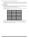
Specifies a coefficient for determining the number of encoder lines per mechanical revolution. The supported values are 1 to
16383. The equation for determining the total number of encoder lines per revolutions is:
nLines = n*10x
where: