


38
Epsilon EP-I Indexing Drive and FM-2 Indexing Module Reference Manual
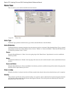
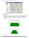
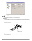
Data Capture
The Data Capture group includes initiate, stop, and graph commands for the graphical monitor.
The “Run” button commands the drive to begin a high speed data capture of the parameters as selected in each of the four
data channels. After the Run button is activated the buffer will fill up to the trigger offset while the words “Filling Buffer”
appear indicating the Graph State. Once the trigger offset level is reached the words “Waiting Trigger” will appear next to
the Graph State indicating that graphical monitor is now ready to be triggered based on the trigger level selected. The Run
button may be activated by the letter “R” on the keyboard.
The “Stop” button will stop the high speed data log after it has been initiated and clear out the buffer that this data was
previously stored in. The Stop button may be activated by the letter “S” on the keyboard.
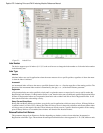
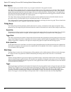
The “Upload and Plot” button will upload captured data from the drive and display this data on a graph. The user should wait
for the Graph State to read “Triggered” before the data is uploaded.
Timing Group
The Timing Group includes parameters which control the size, accuracy, and duration of the capture and upload. These
parameters may be changed using the slider bars but the drive must be downloaded to in order for these changes to take affect.
Sample Rate
The Sample rate slider gives the user control of time spacing for the captured data. To give the user a better idea of what this
number means, the total number of samples and total capture time is displayed on the bottom of this Timing group.
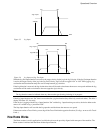
Trigger Offset
This slider corresponds to the number of samples that will be included on the graph display and data capture prior to the actual
trigger. If the Trigger offset slider is completely to the left (min samples), the data capture and graphing will start at the trigger
location. If the slider is completely to the right (max samples) the graph will capture data until the trigger point.
Buffer Upload Size
In the instance that a user would like to save time in an upload, the buffer upload size slider truncates the drive captured data.
If the slider is completely to the right (max) the complete buffer will be uploaded. If the slider is completely to the left, only
1% of the buffer will be uploaded.
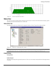
Data Group
The Data Group is used to select which parameters will be graphed as well as which parameter will be used as the data trigger.
If a change is made to any parameters within the Data Group, this change must be sent to the drive via a download.
Channel 1 - 4
Channel 1 through Channel 4 give the user options for parameter display. If parameters with the same units are mapped on
adjacent channels then the graphical display will show these two parameters overlapped on the same x/y axis. If it is desirable
to have two adjacent Channels mapped to separate axis on the graph then the selection (none) should be used on the channel
in between these two parameters.
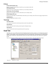
Trigger
Selecting the trigger option button to the right of the channel will cause the graphical capture to trigger the capture off of that
Channel. The “Trigger Level” text box on the bottom of the display will change units to accommodate the selected channels
user units. This trigger level may be changed at any time but the change must be sent to the drive via the “update” or
“download” button. If a manual trigger is desired, set the channel to “None” and select the corresponding trigger option
button. If no trigger is selected the capture will begin when “Run” is clicked and end at the end of the Sample Rate.