


77
Operational Overview
Drive Modifiers
This section describes functions that can modify the operation of the drive.
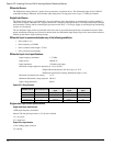
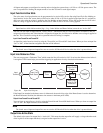
Stop
The Stop input function, when activated, will cause motion to stop regardless of motor direction or the operating mode. The
Stop Deceleration Ramp defines the rate of velocity change to zero speed.
Activating the Stop input function causes the drive to change to Velocity mode. Therefore, if you are operating in Torque
mode, the drive must be tuned to the load to prevent instability when activating the Stop input function.
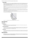
For example, if an application is operating in Torque mode at 3000 RPM, and the Stop input function is activated with a Stop
Deceleration Ramp of 50 revs/s/s, the motor will decelerate to a stop in 1 second.
When the Stop input function is deactivated, the previous operating mode is restored within 400 µs and the drive and
motor will respond immediately with no ramping unless ramping is part of the selected mode.
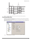
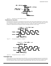
+/- Travel Limits
The + and - Travel Limit input functions will stop motion in the direction indicated by the input function using the Travel
Limit Deceleration rate. This feature is active in all modes. When an axis is stopped by a Travel Limit function, it will
maintain position until it receives a command that moves it in the opposite direction of the active Travel Limit.
For example, the + Travel Limit will stop motion only if the motor is moving + but allows - motion to move off the limit
switch. Conversely, the - Travel Limit will stop motion only if the motor is moving - but allows + motion to move off the
limit switch.
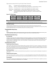
If both input functions are active at the same time, no motion in either direction will be possible until at least one of the inputs
is released.
When either + or - Travel Limit input function is activated, a fault will be logged into the Fault Log, and the drive will display
an “L” on the LED diagnostics display on the front of the drive. Once the axis is driven off the limit switch, the fault will be
cleared and the “L” will disappear.
If both Travel Limit input functions are activated simultaneously, the drive will respond as if the Stop input function has been
activated and will use the Stop Deceleration ramp.
Note
The function of the Travel Limits will be effected by the installation of the Function Module (FM) to the base drive. Please
refer to the particular FM’s reference manual for complete description.
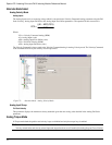
Encoder Output Scaling
This feature allows you to change the drive encoder output resolution in increments of one line per revolution up to the density
of the encoder in the motor. If the Encoder Output Scaling parameter is set to a value higher than the motor encoder density,
the drive encoder output density will equal that of the motor encoder. This feature is enabled by checking the Encoder Output
Scaling Enable check box in PowerTools Pro.
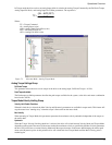
You can setup this feature from the Setup view in PowerTools Pro or using the MODBUS® parameters, Encoder Output
Scaling and Encoder Output Scaling Enable.
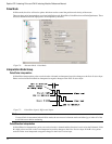
Current Foldback
Note
Current foldback is used to protect the motor and drive from overload. There is one level of current foldback: RMS
Foldback.
RMS Foldback is displayed on the diagnostic display as a "C".