


131
User Defined Motors
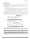
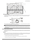
Motor Encoder U Angle
Specifies the electrical angle at which the rising edge of the U commutation track will occur with reference to V
TS
when the
motor is spun in the encoder reference direction.
At power-up the drive looks at the status of the U, V and W commutation tracks and, using this parameter, obtains a crude (±
30 °) estimate of the electrical angle. See “Step 3: Determine Encoder Alignment” for a detailed procedure on how to
determine this parameter.
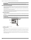
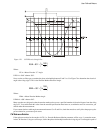
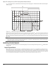
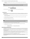
Motor Encoder Reference Motion
Specifies the direction of motion assumed in phase plots of the encoder’s quadrature and summation signals. The supported
values are CW(1) and CCW(0). Your encoder may have the same phase plot but is generated from a different direction of
rotation. This parameter affects the way the drive interprets the quadrature and commutation signals.
Motor Inertia
This parameter specifies the inertia of the motor. The range is .00001 to .5 lb-in-sec
2
. The drive uses this parameter to interpret
the “Inertia Ratio” parameter. “Inertia Ratio” is specified as a ratio of load to motor inertia.
Motor KE
Specifies the Ke of the motor. The units are VRMS/ kRPM. The line-to-line voltage will have this RMS value when the motor
is rotated at 1000 RPM. The range is 5 to 500.
Motor Resistance
Specifies the phase-to-phase resistance of the motor. You can determine this value by measuring the resistance between any
two motor stator terminals with an ohm meter. The range is .1 to 50 ohms.
Motor Inductance
Specifies the phase-to-phase inductance of the motor. The range is 1.0 to 100.0 mH.
Motor Peak Current
Specifies the peak current allowed by the motor. The range is 1 to 100 ARMS. If the peak current of the motor is greater than
30 ARMS, specify the peak as 30 ARMS. The drive will limit the peak current to the drive’s capacity.
Motor Continuous Current
Specifies the continuous current allowed by the motor. It is used to determine the current foldback point and the amount of
current allowed during foldback. The drive can also limit the continuous current to the motor based on the drive capacity.
This means that the operational “continuous current” may be different than the value specified here. The range is 1 to 100
ARMS.
Motor Maximum Operating Speed
Specifies the maximum operating speed of the motor. It is used by the drive to set the default motor overspeed trip point and
to limit the Velocity Command. The Velocity Command is limited to 9/8ths (112.5 percent) of the Motor Maximum
Operating Speed. If the actual velocity exceeds 150 percent of this value, the drive will fault on Overspeed. Typically this
parameter is determined by the encoder bandwidth and/or other mechanical or electrical parameters of the motor. The
maximum value is 11,000 RPM.
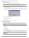
Step 6:Configuring the Drive
Once you have determined the motor parameters and entered them into the MOTOR.DDF file, you can configured the drive
to the user defined motor using PowerTools Pro software. Once PowerTools Pro is started it will read the MOTOR.DDF file
and you will be able to select the non-Control-Techniques motor.