


141
Options and Accessories
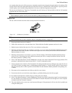
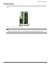
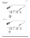
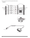
ECI-44 External Connector Interface
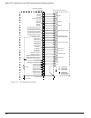
The ECI-44 allows access to all command and input and output signals on the MDS drive module. The ECI-44 should be
mounted close to the drive module and away from any high voltage wiring. The ECI-44 comes complete with the hardware
necessary for mounting to most DIN rail mounting tracks.
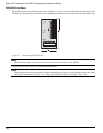
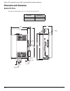
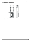
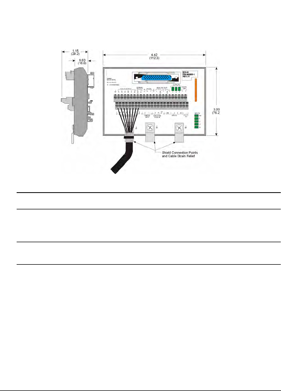
Figure 118: Dimensions of ECI-44
Note
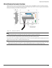
Shield connection points are connected to the shell of the 44-pin “D” connector on the ECI-44.
Use tie wraps to provide a strain relief and a ground connection at the shield connection points.
If you do not wish to use the DIN rail mounting hardware, the ECI-44 can be disassembled and the mounting clips removed.
The ECI-44 wire range is #18 to 24 AWG stranded insulated wire.
Note
Wiring should be done with consideration for future troubleshooting and repair. All wiring should be either color coded
and/or tagged with industrial wire tabs. Low voltage wiring should be routed away from high voltage wiring.