


F3200 Installation & Programming Manual Document No: LT0122
Programming
Page 6-10 5 July 2001 Issue 2.7
6.1.3 PROGRAMMING KEYS
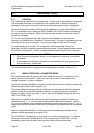
Looking at the keypad (or picture in Fig 2.1.2) the user will observe a 4x4 "numeric" keypad,
and a row of function keys across the bottom. The function keys from "RECALL" to "BELLS
ISOL" all have two functions e.g. "BELLS ISOL/DELETE". In programming mode, these
keys operate the bottom functions i.e. "DELETE", "INSERT", etc. An exception is
"RECALL/(" which will be either "RECALL" or "(" depending on the programming function
selected.
The logic functions in the right hand column of the 4 x 4 "numeric" keypad are used for
entering output logic equations. The symbol and the word represent the same function e.g.
logical "OR" is represented in an equation by the symbol "+".
During text entry the "NOT" key may be used to enter a blank space.
6.1.4 RECOMMENDED PROCEDURE FOR CONFIGURATION &
PROGRAMMING
1. System Design
Determine all system requirements; decide number of 8ZMs, 8RMs, LED Display (if
any); allocate zones and relays. Fill out configuration sheets with programming for
detector type, relay supervision, output logic, etc.
2. Battery & PSU
Calculate battery and PSU requirements as per Section 5. Decide on battery
capacity. Check that physical size of battery fits with proposed mechanical
arrangement.
3. Configure Hardware
With mains power off and battery disconnected. Fit battery test resistor (if required).
Install modules and fit any relay supervision links required.
4. E2 Init
Fit links Lk7, SW1 and turn mains power on to perform Database Initialisation as per
Section 6.3.1. Check that modules configured by Controller match modules installed.
5. Access Database
As per Section 6.3.2, using default code.
6. Assign Access Codes
As per Section 6.4.2. Note that the first code is the master code, and should be
known by the System Designer or Service Supervisor as appropriate.
7. Enter Text
As per Section 6.4.3. Copy names for FIP, zones and relays from configuration
sheets.
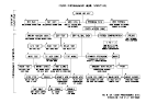
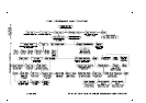
8. Global Parameters
Enter any global parameters different from the defaults such as auto-test inhibit
dates, FIP MCP zone (if other than Zone 1), as per Section 6.4. Fig 6.1.2 can be
used as a flow chart. Work from top to bottom, left to right.
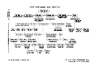
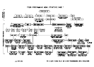
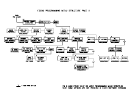
9. Enter System Configuration Parameters
Refer to Fig 7.1.1. Enter all the circuit, zone, output logic, relay supervision and
RZDU parameters from the configuration sheets that differ from the defaults. Start at
the left side of Fig 7.1.1 (circuits), and work from left to right through each branch,
starting at the lowest numbered item (e.g. zone, relay) and stepping through to the
largest number for each item configured.