


F3200 Installation & Programming Manual Document No: LT0122
Programming System Configuration
Page 7-10 5 July 2001 Issue 2.7
VOLTAGE BANDS (CONTINUED)
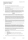
Voltage bands and their interpretation for modes 1, 2 and 3 are shown in Table 7.2.1
following.
Band Voltage
Status Default Status
B5 21-22VFault (Open Circuit) Fault (Open Circuit)
B4 17.5-21V Normal Normal
B3 13-17.5V Programmable Normal (V1.XX software)
Instant alarm (V2.XX software)
B2 3-13V Alarm Alarm
(Detector Operated) (Detector Operated)
B1 0-3V Programmable Instant Alarm (Manual)
TABLE 7.2.1
AZC VOLTAGE BANDS FOR MODES 1-3
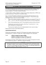
In Mode 4, for AZC normal the voltage is in B5 with pulses into B4 due to the active end-of-
line device. B2 is Alarm (valve operated). B3 is programmable to Alarm or Fault only
(default is Alarm). B1 is programmable (default is Fault). All other conditions are Fault
(Tamper).