


F3200 Installation & Programming Manual Document No: LT0122
Installation & Wiring
Page 8-26 5 July 2001 Issue 2.7
8.10 SLIMLINE NDU (FP0714) WIRING
MCP Connection
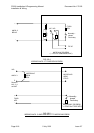
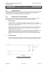
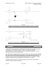
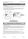
A slimline NDU has the facility for connection of an MCP, but the MCP has to be mounted on
the wall, immediately adjacent to the NDU.
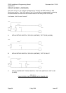
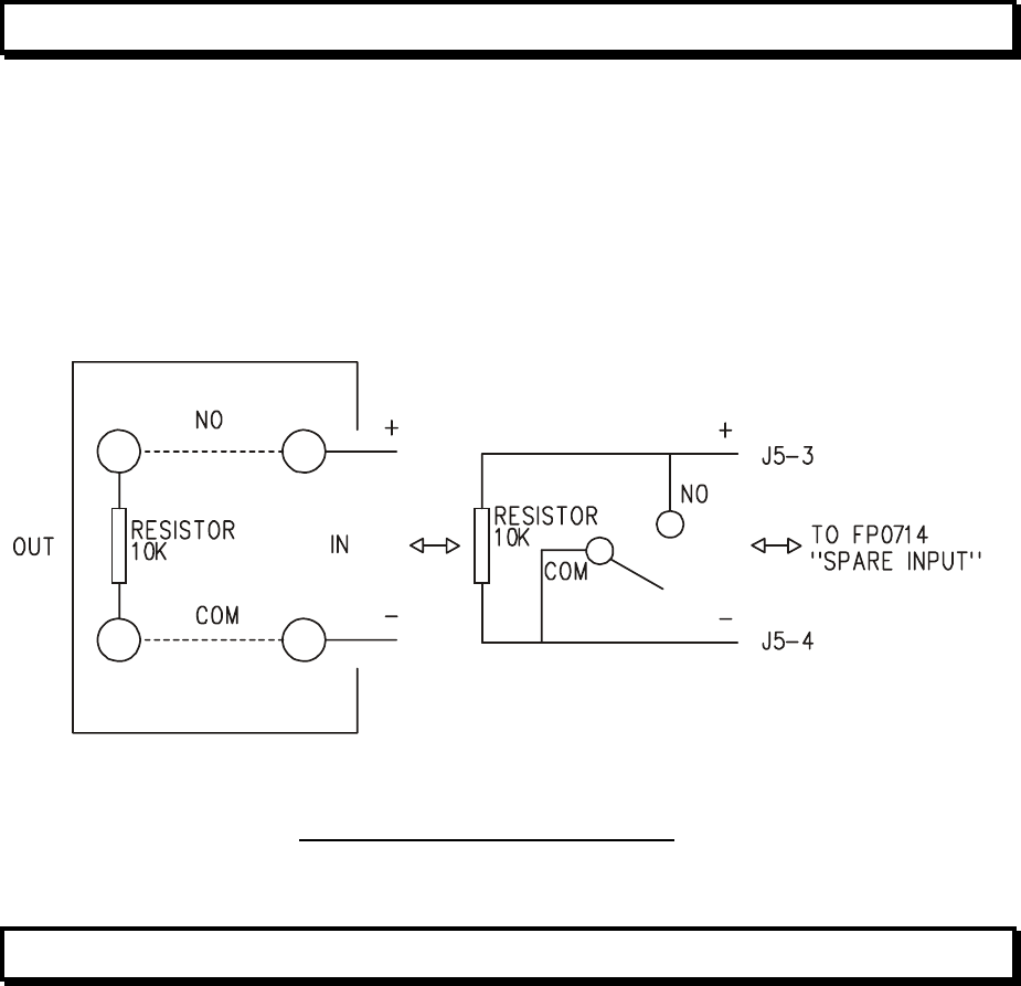
Connection is made to pins 3 & 4 of J5, the 4 way "Spare Input Connector" on the NDU
Controller/Display Bd. The wiring to the MCP itself is detailed in the figure below. For an
NDU in New Zealand mode refer to Chapter 12.
FIG 8.9.1
FP0714 NDU MCP CONNECTION
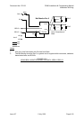
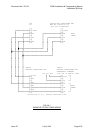
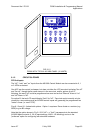
8.11 INSTALLATION OF 19" NDU (FP0733)
The NDU is available as a 19" rack mount kit (FP0733). This must be installed as follows to
meet the EMC requirements.
Using the RS485 board as a template, drill 4 x ∅3.5mm holes and deburr. Scrape away any
paint on the inside face and mount the metal standoffs using 4 M3 x 6 screws and
shakeproof washers. Mount the RS485 board onto the standoffs using M3 x 6 screws and
M3 crinkle washers.
Mount the 4U inner door onto the 19" rack and earth to the cabinet using the earth lead
supplied.
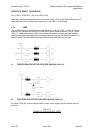
Run the 10 way FRC from J7 (Network 1) on the Controller to J1 on the RS485 board,
keeping it tight against the cabinet metalwork by using FRC clamps.
Run +24V to the J5 terminals on the Controller, and the network cables to J3 on the RS485
board. Connect any screen on the network cables to the 0V ISO terminal on the RS485
board.