F3200 Installation & Programming Manual Document No: LT0122
New Zealand Operation
Page 12-4 5 July 2001 Issue 2.7
12.3 MANUAL CALLPOINT (MCP)
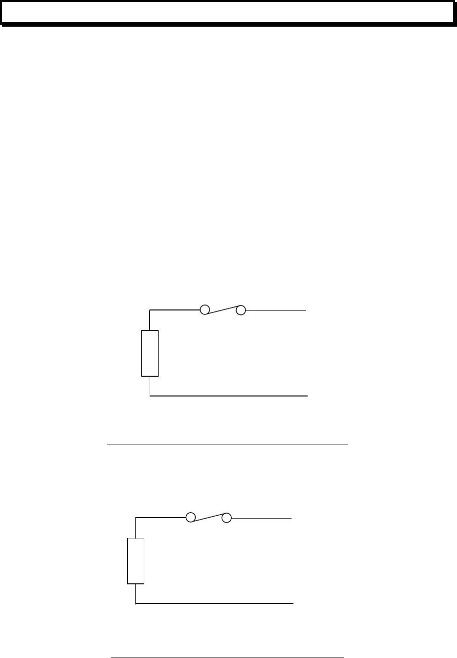
An NDU with a MAF board may have an MCP connected to the MAF board (refer Fig 12.3.1
for wiring).
An NDU without a MAF board may have an MCP connected to screw terminals 3 and 4 of
standalone connector J5 on the Controller board as shown in Fig 12.3.2.
The MCP is disabled by default. To enable it, it should be mapped to one of the 16 alarm
zones (1-16) on the NDU. To map the MCP to a zone, select option 3:Global data from the
main programming menu, then option 2:FIP MCP.
The zone the MCP is mapped to can be programmed with a name, whether it is
latching/non-latching, maf/non-maf, etc (refer to Fig 7.1.1B for zone options). If the zone is a
status-only zone, then the MCP input can be used as a general purpose input, and its status
can be accessed in output logic by using the zone status tokens (ZnA, ZnF, ZnW, and ZnI)
of the zone it maps to.
There is a one second delay applied to any change of state on the MCP input. If the zone
the MCP maps to is a MAF zone then a brigade alarm will result after this time delay.
FIG 12.3.1
NZ MODE MCP WIRING FOR NDU MAF BOARD
FIG 12.3.2
NZ MODE MCP WIRING FOR “SLIMLINE” NDU
RESISTOR
2K7
- J6-4
+ J6-3
C NC
MCP
To connector J6 on
the MAF/PSU board
RESISTOR
10K
- J5-4
+ J5-3
C NC
MCP SWITCH NORMALLY CLOSED
“STANDALONE” Connector
J5 on the Controller


