


Document No: LT0122 F3200 Installation & Programming Manual
Applications
Issue 2.7 5 July 2001 Page 9-23
9.4.3 INTRINSICALLY SAFE DETECTION
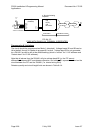
There are two types of device which may be inserted in a detector circuit between the FIP
and the detectors to limit the electrical energy flow into the area and provide IS detection:
1) Galvanically (transformer) isolated repeaters (isolators).
2) Zener barriers (shunt barriers with fuses). These limit the circuit voltage relative to
earth, and the circuit current.
Although Zener barriers are cheaper than isolators they require a special Intrinsic
Safety Earth, and precautions, and are therefore not recommended.
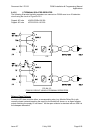
9.4.3.1 ISOLATED REPEATERS
There are several options for using isolated repeaters, each with differing limitations and
expense.
The options are:
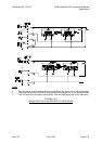
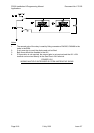
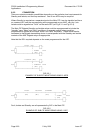
1. Use a 6 terminal isolating repeater where large numbers of smoke and/or flame
detectors are required (see Section 9.4.3.2).
2. Use a lower-cost 4 terminal isolating repeater and a ZAU401 (Rev 2) where lower
numbers of smoke and/or flame detectors are required (see Section 9.4.3.3).
3. Use a 4 terminal isolating repeater where all detectors generate a short circuit alarm
condition (see Section 9.4.3.4).
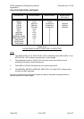
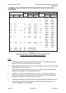
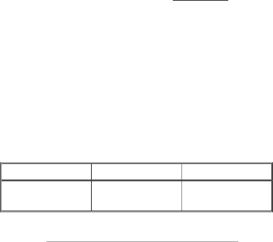
For these the total capacitance and inductance of the detectors and cables on the IS circuit
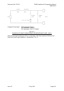
must be less than that specified in Table 9.4.1. The gases and vapours in each Gas group
are listed in IEC 79-12.
GAS GROUP MAX. CAPACITANCE MAX. INDUCTANCE
Class IIA or Group D
Class IIB or Group C
Class IIC or Group A or B
1.04uF
0.39uF
0.13uF
31.9mH
12.6mH
3.6mH
TABLE 9.4.1
MAXIMUM CAPACITANCE & INDUCTANCE PER IS CIRCUIT
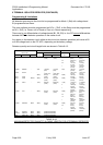
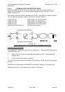
For isolated repeaters, the cable core to core capacitance can be used, rather than core to
earth which, for bunched conductors on metal trays, may be higher. (Note that for Zener
barriers, the core to earth capacitance is relevant). The values used in this section for a
typical TPS pair, or multicore cable (unshielded) are:
TPS C = 100nF/km (i.e. 100 pF/m), L = 0.8mH/km
Cable manufacturers may quote differing values for specific cables.
It is the responsibility of the System Engineer to check that the cable
used has values less than or equal to the above values, and that the total capacitance and
inductance for each circuit meet the requirements.
The values specified for the detectors are shown in Table 9.4.2.