


F3200 Installation & Programming Manual Document No: LT0122
Installation & Wiring
Page 8-8 5 July 2001 Issue 2.7
8.2 FIELD WIRING
8.2.1 GENERAL
Cabling should comply with all the points in AS1670.1, Section 8.17. Note the requirements
for segregation and identification.
The cabling should, in general, be of not less than 0.75mm² cross sectional area, insulated
and have red PVC sheathing. Joins should only occur in enclosed terminal boxes, and it is
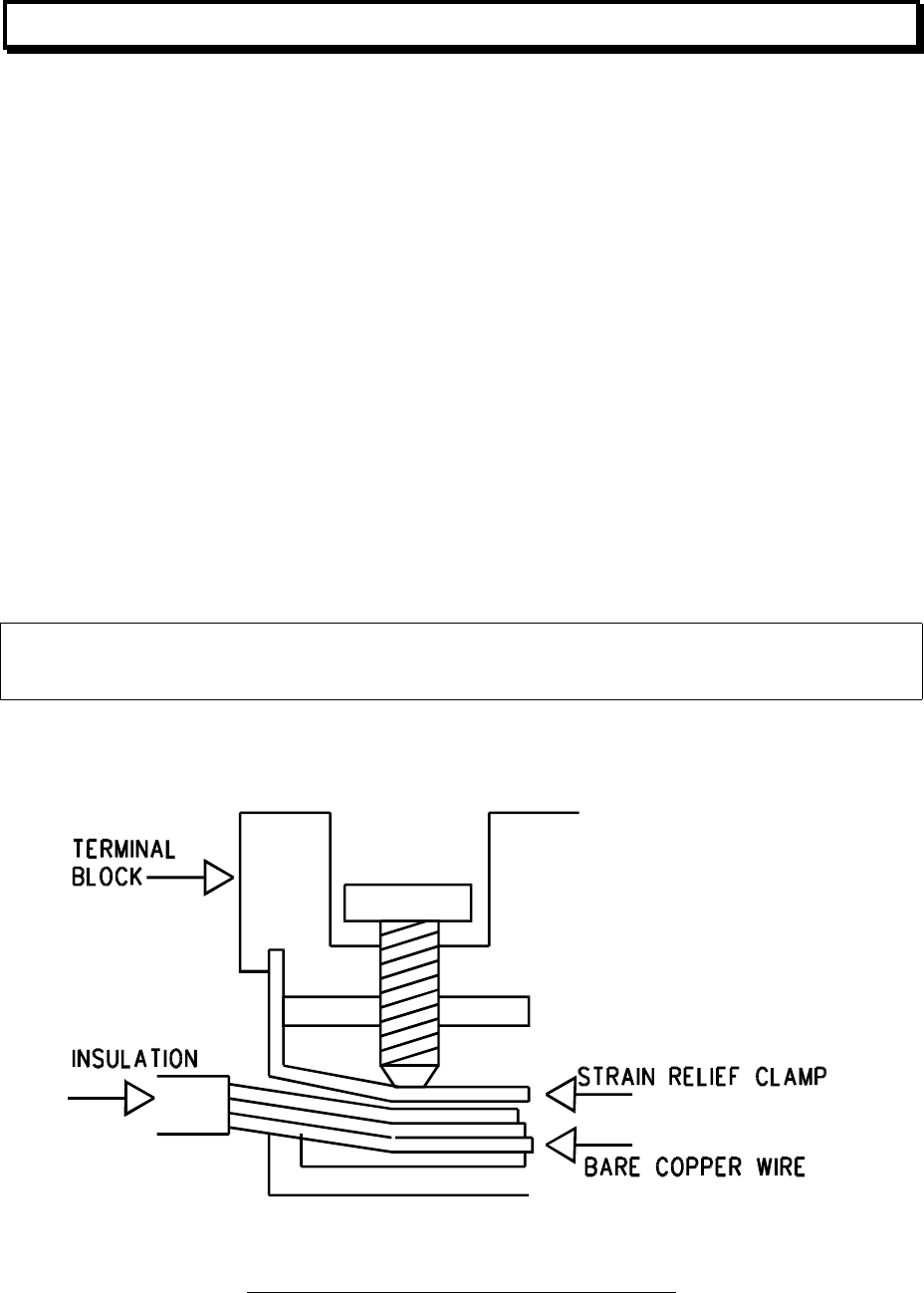
important that all terminations be good. I.e.
no bare wire protruding from the terminal;
no insulation inside the clamp part of the terminal;
wire not cut or "nicked" during stripping;
wire not soldered;
wire not "doubled back" in the demountable terminals with leaf type strain relief
clamps;
all terminals firmly tightened;
neat service loop;
goose neck where servicing requires cable movement;
coil of spare cable in wall/ceiling to allow for mistake/alteration.
Note that it is best to carry out parts of the initial survey during installation, in particular,
resistance and insulation testing.
W A R N I N G
Apart from the Mains supply to the FIP,
only ELV cabling
should enter the cabinet.
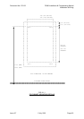
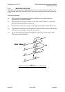
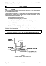
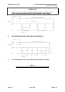
FIG 8.2.1
SCREW TERMINAL CABLE CONNECTION