


Document No: LT0122 F3200 Installation & Programming Manual
Applications
Issue 2.7 5 July 2001 Page 9-19
9.3 SUB FIP MONITORING
9.3.1 GENERAL
A sub-FIP is a Fire Indicator Panel (e.g. a Gas Flood Panel) which may not be connected
directly to the Brigade, but repeats its common conditions (e.g. Fire, Fault) to another FIP.
AS1670.1 allows for the cabling from FIP to sub-FIP to be less than 0.75sqmm, and the
resistance may be considerably greater than that used in standard detector circuits. The
"Low Current Mode" for an F3200 AZC allows supervision of sub-FIPs on circuits with high
resistance.
The limitations caused by the resistance in sub-FIP monitoring circuits are shown in the
following 3 cases.
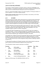
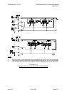
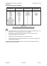
1. Loop Resistance Less than 150 Ohms
For a detector circuit programmed for standard mode the maximum loop resistance is 50
Ohms, but where there is no detector load (i.e. clean contacts are used) the resistance may
be up to 150 Ohms.
Therefore it is recommended that for loop circuits of less than 150 Ohms, "standard mode"
be used for sub-FIP monitoring.
All voltage bands are potentially usable, but it is recommended that B3 NOT be used for any
condition as the circuit voltage drop of up to 2.5V needs to be allowed for. B2 can be used
with a 5V6 or 6V8 zener diode to detect Alarm i.e. ZnA, and B1 can be used to detect Alarm
(ZnD) or Instant Alarm (ZnM).
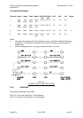
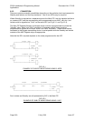
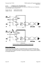
2. Loop Resistance of 150 Ohm to 800 Ohm
For this resistance range the AZC has to be programmed into "Low Current Mode", and
voltage band B1 should be programmed as Fault or Alarm but must not be used to detect
the Fault signal from the sub-FIP (i.e. by shorting the circuit with the Fault contacts).
Shorting the circuit at the sub-FIP will cause B2 Alarm.
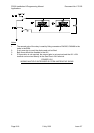
Because the voltage drop in the circuit wiring is between 3.8V and 12V, depending on loop
resistance, it is recommended that B3 not be used to detect a signal (for safety sake it is
advisable to program B3 as Alarm and B1 as Alarm or Fault. Note that only a short
somewhere within the circuit wiring can cause B1).
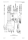
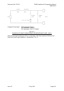
3. Loop Resistance of 800 Ohm to 2000 Ohm
For this resistance range the AZC has to be programmed into "low current mode", and the
voltage band B3 has to be programmed as Alarm. Shorting the circuit at the sub-FIP will
cause either a B2 or B3 Alarm depending on the loop resistance (nominal B2/B3 threshold is
1100 Ohm).
B1 may be programmed as Fault or Alarm, but must not be used to detect the Fault signal
from the sub-FIP.