


Document No: LT0122 F3200 Installation & Programming Manual
Installation & Wiring
Issue 2.7 5 July 2001 Page 8-15
8.5 WARNING SYSTEM WIRING
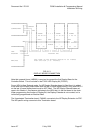
The typical configuration allocates the Ancil 3/Bells relay to drive the Warning System, and
has links Lk2-4 fitted so that a switched 24V output is available at the +/- terminals. The
supervision allows for up to 3 branches of wiring, with each requiring its own end of line
resistor (EOLR). The value of the EOLR varies with the number of branches such that the
combined total is always 3K3. The EOLR must be fitted at the end of each branch.
Branches EOLR
13k3
26k8
3 10k
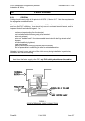
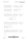
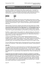
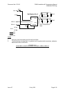
The Ancil 3/Bells output can be used to directly control alerting devices such as sounders
(that generate tones to AS2220), AVIs, strobes etc. If each device does not have an internal
series diode then a series diode must be fitted at each device. The diode must be rated to
carry the current of the device. Fig 8.5.1 shows a dual branch system with diodes fitted to
each device.
Note the Vigilant AVI requires an external series diode to be fitted at each device. Multiple
AVIs cannot presently be synchronised because the sync line carries the signal and is not
supervised (a revision of this is planned.) Refer to Fig 8.5.1. The AVIs should be used with
only two wires (+24V and EVAC-, or +24V and ALERT-), which is 3 Wire mode, but may
have to be used in 2-wire mode with the +ve lead connected to ALERT- (EVAC+) and the
–ve to EVAC- to get the required selection (e.g. Evac tone, top and bottom lamps both on).
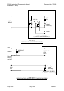
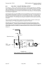
The Bells +/- output is limited to 2A dc resistive max. (Note that loads such as AVIs, Mini-
Gens are considered resistive, whereas loads such as Solenoids and bells are inductive). A
load of up to 5A dc resistive can be accommodated by use of a Bell Monitor Board and a
separate, 6A dc, inline fuse. See Fig 8.5.6.
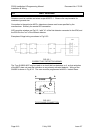
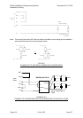
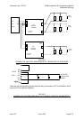
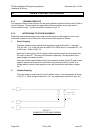
A relay on an 8 Relay Module can also be used to control and supervise a circuit of
evacuation devices. This is shown in Figure 8.5.3. Note that both poles of the relay are
needed and the relay needs to be programmed so that it doesn’t supervise the wiring when it
is activated (requires V2.09 or greater software). Although shown with only 1 circuit of
evacuation wiring, it can actually support two branches, using a 27k EOL resistor on each.
The Ancil 3/Bells relay can also be used to activate (and supervise) external tone generation
devices such as Mini-Gen, T-GEN, Microvac and QE90 this is covered in following sections.
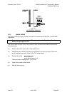
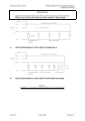
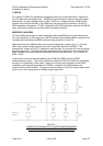
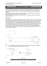
MINI-GEN
The Vigilant Mini-Gen has an internal diode and can be connected with up to three branches
of speakers as per the instructions included with each unit. The 10k EOLR fitted to each
speaker line must be rated at 2W and is supplied with the unit. Refer Fig 8.5.2. If less than 3
branches are required, 10K 2W is still fitted to the end of each branch, with the other EOLRs
being fitted to the +/- dc input terminals of the furthest Mini-Gen. Refer to the instructions for
details.
The Mini-Gen can be link selected to produce an Alert tone, an Evac tone, an automatic
change from Alert to Evac after 1 minute, or an automatic change after 3 minutes. If desired,
it can be configured to produce Evac, with a relay switching the tone to Alert. For this, a mini-
jumper is fitted to link V, and the supplied 3 way connector fitted to link A/B with normally
closed relay contacts shorting pin 2 to 3 (position B) to produce Alert. When the contacts
open, the tone will change to Evac. Note that this applies only to Mini-Gen Rev 3 bds with
V2.00 or greater software, and for internal wiring of the relay to the Mini-Gen (i.e. the Mini-
Gen must be mounted within, or adjacent to the FIP.)