


Document No: LT0122 F3200 Installation & Programming Manual
Applications
Issue 2.7 5 July 2001 Page 9-7
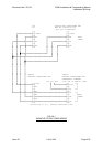
CIRCUITS & ZONES (CONTINUED)
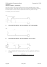
R5 = Z15D + Z15N.Z5A.^ (Z1:4(1)A+Z6:10(1)A)
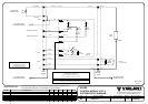
Note also, that if the interposing relay (fan control input) is 24V at less than 100mA then an
open collector (O/C) may be used as per circuit 1 of 1945-1-1/4 following.
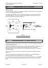
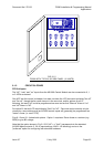
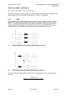
9.1.4 LEDS
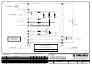
The 3 LEDs may be: switched directly as per circuits 1 and 2 of 1945-1; driven off 3 open
collector (O/C) outputs or driven off 2 O/Cs with a Zener diode as shown in Fig 9.1.6 and
1945-1-3. Note that where the FIP has a number of detector circuits, the open collector
outputs associated with these AZCs may be used for driving the AS1668 LEDs and so it
doesn't matter if the AS1668 panel requires more open collectors than circuits.
+VBF
─┬─
│ 3K3 ┌──┐
RUN ├───────>├────█████────────┤ │ OC1
│ Red └──┘
│ 3K3 ┌──┐
FAULT ├───────>├────█████────────┤ │ OC2
│ Yellow └──┘
│ 3K3 ┌──┐
STOP └───────>├────█████────────┤ │ OC3
Green └──┘
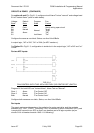
A. THREE OPEN COLLECTOR O/PS PER FAN (Ref 1945-1-4).
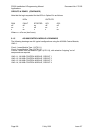
+VBF
─┬─
│ 3k3 RUN ┌──┐
├────█████───┬───>├────────┤ │ OC1
│ │ Red └──┘
│ STOP
∇
Green
│ ╒╧╕
│ │ │3V9 ZENER
│ └┬┘
│ ─┴─
│ 3K3 0V FAULT ┌──┐
└────█████───────>├────────┤ │ OC2
Yellow └──┘
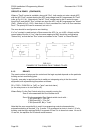
B. TWO OPEN COLLECTOR O/PS PER FAN (Ref 1945-1-3).
For other LEDs (eg. Chrome Bezel LEDs) a lower value (higher current) resistor may be
required.
FIG 9.1.6
WIRING OF FAN CONTROL LEDS