


F3200 Installation & Programming Manual Document No: LT0122
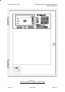
System Description
Page 2-10 5 July 2001 Issue 2.7
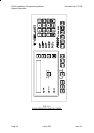
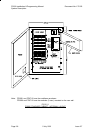
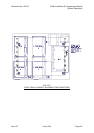
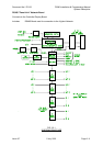
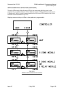
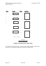
2.3 SYSTEM STRUCTURE
2.3.1 PCB MODULES
The 6 printed circuit boards which are used in an F3200 are as follows:
Controller/Display
Mounts on 4U inner door.
Includes: LCD, status LEDs and buzzer
keypad connection
5Vdc supply
voltage monitors for battery charger
microprocessor & memory
serial I/O bus control for all other modules
reference voltage generation for I/O modules
UARTs and serial port electronics
real time clock calendar integrated circuit
FRC connection to other modules.
MAF/PSU
Mounts on cabinet rear wall.
Includes: battery charger/PSU
22V regulator for detector circuits
Brigade & Ancillary relays and supervision circuitry
MCP & door switch inputs
screw terminals (most demountable) for field wiring
FRC connection to other modules.
8 Zone Module
Mounts on cabinet rear or in cardframe.
Includes: electronics to I/F to 8 Alarm Zone Circuits (AZCs)
8 open collector auxiliary outputs
demountable screw terminals for field wiring
FRC connection to other modules.
8 Relay Module
Mounts on cabinet rear or in cardframe.
Includes: 8 relays and supervision circuitry
demountable screw terminals for field wiring
FRC connection to other modules.
16 Zone LED Display
Mounts on 7U inner door.
Includes: 16 sets of 3 LEDs
electronics to control the LEDs (serial bus)