


F3200 Installation & Programming Manual Document No: LT0122
System Description
Page 2-12 5 July 2001 Issue 2.7
2.3.2 INTER-CONNECTION & STRUCTURE
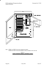
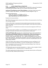
A basic F3200 system
has one Controller/Display, one MAF/PSU, and one 8 Zone Module,
all connected by Flat Ribbon Cable (FRC) on a common Input/Output (I/O) Bus.
Additional 8 Zone Modules and/or 8 Relay Modules
can be fitted to the I/O bus, with a
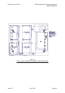
maximum of eight 8 way modules. This is shown in the block diagram of Fig 2.3.1.
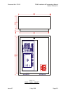
The physical maximums are:
three 8 way modules in an FP0550 or FP0712.
four 8 way modules in an FP0583 (with restrictions)
eight 8 way modules in an FP0551 or FP0713.
Expansion is from top to bottom.
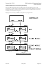
The I/O Bus Out of one module connects to the I/O Bus In of the next module via the 20 way
FRC provided (LM0053).
No link or "End of Bus" is required on the last module because the data from the furthest
output shift register is fed into the furthest input shift register via the wrap-around resistor as
shown in Fig 2.3.2.
Refer to Section 3.1.3 Specifications for detail on the structural arrangement of AZCs and
relays.
To further extend these capabilities, up to 64 F3200s may be networked together, with full
sharing of information and remote control of each panel by a master panel.
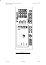
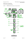
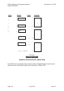
16 Zone LED Display bds
are driven from a separate serial bus on the Controller/Display.
They receive power from the MAF/PSU via two power leads. Where more than one is
required they are connected in series (up to 4 maximum) from right to left (as viewed from
the front) on the FIP. The 26 way FRC from J13 of the Controller goes to J1 ("From
Previous") of the right hand Display Bd. Zone 1 (default) corresponds to the top LEDs on
the left hand Display Bd. The last board requires the "end of bus" minijump connector to be
fitted. Note that a special FRC cable is required to connect the Controller Board to the first
Display Board (LM0092).
Where LED Display bds are fitted, the default programming requires one Display bd (16
zones) for every two 8 Zone Modules, i.e. one for 1-16 zones, two for 17-32 zones, etc.
Zone 1 corresponds to the top row of 3 LEDs on the left most Display. Zone 2 to the row
below it, etc, (top to bottom, left to right).
LED Display bds may also annunciate relay status, i.e. Alarm <-> relay energised, Isolated
<-> relay isolated, Fault <-> relay wiring fault (i.e. supervision fault).
The default programming for displaying both zone and relay status requires one Display bd
for every two 8 way modules (zone and relay).