


Document No: LT0122 F3200 Installation & Programming Manual
Programming System Configuration
Issue 2.7 5 July 2001 Page 7-13
7.4 PROGRAMMING OUTPUTS
7.4.1 GENERAL
The F3200 outputs (Ancillary Relays, MAF Brigade Relays, 8 Zone Module open collectors
and 8 Relay Module relays) may be programmed to operate on a logic equation of zone and
FIP status. Zone LEDs may also be controlled by an output logic equation. Output logic
equations may also be used to isolate, de-isolate or reset zones. The Ancillary Relays
(including Anc3 /Bells) and the Open Collector outputs each have a default logic equation
but the module relays do not. By default, Ancillary Relays and Bells operate on an alarm on
any zone mapped to operate that output. By default, open collector output n is active when
zone n is in alarm. The LEDs on the 16 zone LED display boards may be controlled by
output logic using a relay equation where the relay number is in the range 65 to 256.
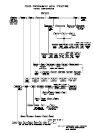
The outputs which can be programmed are shown in the Output Logic Menu in Fig 7.1.1 and
described in Section 7.4.6.
The logic equation takes the form of:
Output = [operand] operator [operand] operator [operand] ...
E.g. RL1 = Z3A + Z4A means that Module relay number 1 will energise when zone 3 is in
alarm or zone 4 is in alarm (or both). Zone 3 alarm and zone 4 alarm are operands (inputs)
and the logic operator is OR (+).
Some examples of equations are shown in Section 7.4.4.
Output Logic : Number of "small" equations 289 maximum
Number of "()" per equation 14 maximum
Equation Size (note 1) 100 bytes max
Number of variables available 256
Number of network variables 128 per SID
Number of seconds timers available 64 (1-64)
Number of minutes timers available 8 (65-72)
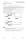
Type of timer (see following) Stretch/Pulse
Time range of timers 0-250 seconds/minutes
Error margin of seconds 0-1 sec plus
timers 1-64 O/P Logic Time
Error margin of minutes timers 65-72 0-1 Minute
Output Logic Processing Time 0-1 second
(refer to note 2 following)
1. The maximum size of an equation is approximately 30-40 operands plus operators.
It is 100 token bytes, where most operands use 2 bytes, and operators use 1 byte.
2. The Controller continually "updates" the status of the inputs to the output logic
equations, processes the equations, and updates the resultant outputs. The
processing time taken is dependent on the number and size of the equations.
A timer is started by a logic equation, and then operates the output via another logic
equation. There is a processing delay added to the timer delay.
For a system with only 10-20 small to medium sized equations, the processing delay
should be of the order of 100 msec, and an approximate 1 second timer can be used.
For a system with the maximum number of equations the processing time may delay
beyond the 1 second stated, so that a delay programmed as "1 second" would cause
a real delay (from input event to output options) in excess of 3 seconds.