


F3200 Installation & Programming Manual Document No: LT0122
Applications
Page 9-2 5 July 2001 Issue 2.7
9.1 AS1668 AIR CONDITIONING CONTROL
9.1.1 GENERAL
The following features of F3200 allow it to be easily adapted to Air Conditioning Plant
Control (referred to as AS1668 which is the relevant Australian Standard):
• 19" Rack mounting cabinet with standard light grey blank panels available,
including 9½U (plastic), 7U metal (hinged), 4U metal, 3U metal;
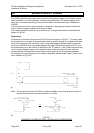
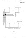
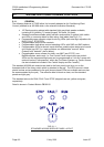
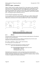
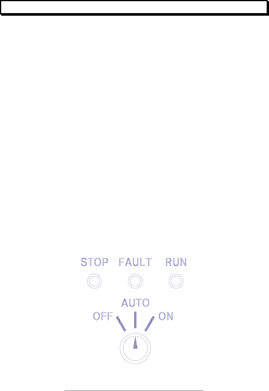
• Standard modules available which include a pcb module (3 options) with switch
and LEDs, a connector block for field wiring, and labels (see Fig 9.1.1).
• Programable open collector output for driving LEDs (can enter logic equations for
RUN, FAULT, STOPPED);
• Programmable relays for fan controls;
• Programmable time delays on duct sampling AZCs, with RAD and SAD options;
• Programmable AZCs for control inputs with two useable alarm states plus normal
(plus faults) per AZC (i.e. logic equations can differentiate "manual" alarm
(instant) from "detector" alarm (alarm);
• Programmable zones, allows non-latch, non-MAF (non-FFCIF), non-
Bells/Ancillaries, status only (i.e. Fan Control Panel output relays can switch
AZCs and the corresponding zones can be programmed as "non-fire" zones with
optional levels of "transparency" within the Fire Alarm System e.g. Faults, Alarms
can be included/not included in the "totals" display and the "recalls").
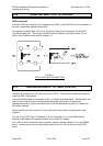
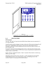
The standard AS1668 pcb modules are held to the front panel (rear) by a nut on the
threaded shaft of the rotary switch which is attached to the pcb. The LEDs mount in black
plastic bushes and are soldered to the pcb (chrome bezel LEDs are available and can also
be accommodated by the pcb). The adhesive label is black on clear, and the standard
panels are light grey.
The standard colours for RUN, FAULT and STOP (stopped) are red, yellow and green,
respectively.
Detail is shown in Product Bulletin PBG0015.
FIG 9.1.1
STANDARD AS1668 MODULE PANEL LAYOUT