


Document No: LT0122 F3200 Installation & Programming Manual
Installation & Wiring
Issue 2.7 5 July 2001 Page 8-23
│ │ ─┬─
┌┴┐
│ │ │ │
└┬┘
┌─┴─┐ +┌─┴─┐ │
OCn │ ├───────────────────────────────┤ ├───┴──────────────────────
└─┬─┘ └─┬─┘
│ Cct n
│
│ EOLR
│
┌─┴─┐ ┌─┴─┐
0V │ ├───────────────────────────────┤ ├───── 0V
└─┬─┘ └─┬─┘
F3200 │ │OTHER EQUIPMENT
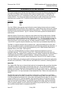
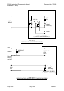
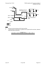
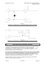
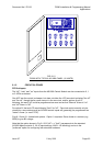
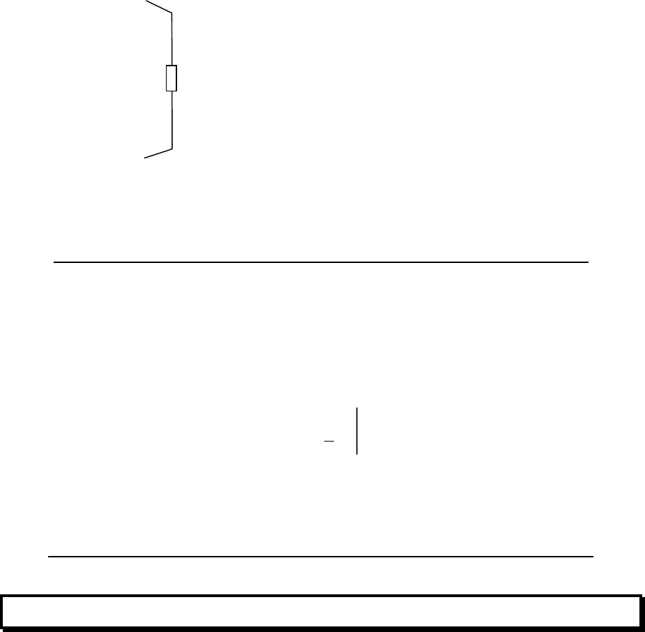
FIG 8.7.2
EXAMPLE OF INTERFACING TO OTHER EQUIPMENT, DIRECT COUPLING
┌───┐
+VBF │ ├───────────────────────────┐ OPTOCOUPLER
└───┘ ┌┴┐ ┌───┐
RESISTOR │ │ ┌─────┤ │+
E.G. 4K7 └┬┘ │ └───┘
│ / C Cct n
∇
>
┌───┐ │ \ E ┌───┐
OCn │ ├───────────────────────────┘ └─────┤ │-
└┬──┘ └─┬─┘
F3200 │ │OTHER EQUIPMENT
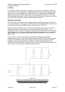
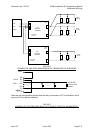
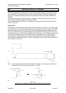
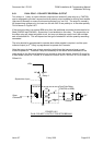
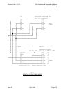
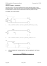
FIG 8.7.3
EXAMPLE OF INTERFACING TO OTHER EQUIPMENT, OPTICAL ISOLATION
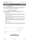
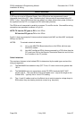
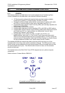
8.8 ASE INSTALLATION AND WIRING
A Vigilant ASE may be mounted in an F3200 panel or an NDU in a large cabinet. Two kits
are available, namely KT0199 and KT0212. Both are 3U hinged front panels
accommodating 1 or 2 ASE or V-Modem units (or a combination) respectively. The kits
include mounting parts and fitting instructions.
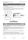
The ASE should be wired directly off the battery via its own fuse. Wiring of the ASE FP0740
EOL unit is as per the ASE installation instructions. The red wires are wired across the MAF
Alarm relay NC and C terminals, the yellow wires across the MAF Fault relay NC and C
terminals, and the blue wires across the MAF Isolate relay NC and C terminals. No other
connections to these relays are permitted when the ASE EOL unit is used.
Locating the ASE remote from the panel has additional requirements under AS4428.1
(Clause 2.10) that currently cannot be met.