


F3200 Installation & Programming Manual Document No: LT0122
Installation & Wiring
Page 8-4 5 July 2001 Issue 2.7
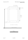
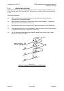
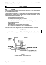
8.1.2 CARDFRAME INSTALLATION
A KT0072 Cardframe upgrade kit can be fitted to a 15U F3200 to allow it to take more than
three 8 way modules. In older versions, the cardframe mounts directly to the rear of the
cabinet. In newer versions, the cardframe is fitted to a gear plate that may be removed when
the cabinet is mounted to the wall.
1.
If the system does not require large batteries
(refer to Section 4.3.4) it may be
fitted as follows, using a pop rivet gun and M4 nut driver. With FIP power not
connected, batteries not fitted.
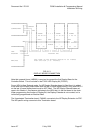
a. For an older cabinet that is removed from the wall:
1. Remove all 8 way modules.
2. Remove the 3 sets of PCB standoffs on the left side rear of the cabinet.
3. Remove the M4 nuts, washers and PCB spacers from the 3 M4 studs on the
left side of the cabinet.
4. Fit the Cardframe over the studs with the M3 bushes on the right hand side.
5. Refit the 3 PCB spacers, washers and nuts on the inside (do not yet fully
tighten).
6. From the cabinet rear, with the Cardframe firmly against the cabinet, insert
the 3 pop rivets provided into the holes in the Cardframe, and rivet.
7. Tighten the M4 nuts on the studs.
b. If the cabinet is mounted to the wall the procedure is the same as above except:
In step 2, the standoffs need to be cut off.
In step 6, the rivets need to be inserted from the front.
c. For a newer cabinet with a gear plate, the procedure is similar except that the gear
plate is to be removed and the cardframe fitted to it.
2.
If a system requires the Cardframe to be removable to allow the
fitting/removing of larger batteries,
then the procedure is similar to that described
above, but, instead of pop rivets, M4 screws should be used as follows:
1. Use three M4 x 10 or M4 x 12 screws, with nuts, and shakeproof washers.
2. Fit the screws with the heads outside the cabinet rear, washers and nuts
inside the Cardframe.
3. Put some Locktite (or equivalent power glue) under the heads of the screws
(but
not
on the threads).
4. Tighten the nuts on the screws initially holding the heads of screws.
5. Subsequent removal of the nuts (after the Locktite has dried) should be
possible without removing the cabinet from the wall.