


Document No: LT0122 F3200 Installation & Programming Manual
Installation & Wiring
Issue 2.7 5 July 2001 Page 8-5
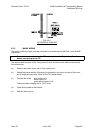
8.1.3 MODULE INSTALLATION
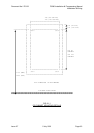
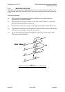
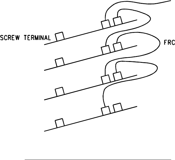
The 8 Zone Modules and any 8 Relay Modules are fitted in order, from top to bottom. The
FRCs fit under each PCB, from BUS OUT of the top one to Bus IN of the next one (see Fig
8.1.2).
Observe the following:
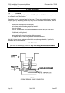
(a) When mounting to the cabinet the M3 mounting screw per module should be
tightened firmly to earth the module.
(b) Modules and FRCs need to be fitted one at a time in the Cardframe. It is easier to
start from the bottom module and work up.
(c) Care should be taken not to scrape an FRC against the bottom of the PCB above it.
(d) There are redundant slots in the Cardframe to allow for either 6 module even spacing
or 8 module even spacing. Choose the correct slots.
(e) On the Cardframe finger tighten the single M3 screw firmly into the notch in each
PCB as this earths the module.
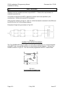
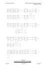
FIG 8.1.2
MODULE CONNECTION WITHIN A CARDFRAME