F3200 Installation & Programming Manual Document No: LT0122
Applications
Page 9-14 5 July 2001 Issue 2.7
AVI SIGNS (CONTINUED)
Function Input Lamps Tone Mode DIL SW
On
DIL Sw
Off
Lk1,2 Lk3 Lk6 Notes
1Alert-
Both
Top
Both
Alert
Evac
3-wire
std
1,3,5,6 2,4,7,8 1-2 1-2 On
2Alert-
Both
Top
Both
Alert
Evac
3-wire
std
1,3,5,6 2,4,7,8 1-2 1-2 On
3 Evac- Both Evac 2-wire 2,3,5,6 1,4,7,8 2-3 1.2 Off b.
4 Alert- Both None 3-wire
spcl
1,3,5,6,
8
2,4,7 1-2 2-3 On
Notes
a. The option of top lamps with Evac tone for one input, and both lamps with Evac tone
for the other, is not directly supported. But it can be arranged by mounting the AVI
upside down.
b. For this configuration the +ve supply is wired into Alert-, not +24V.
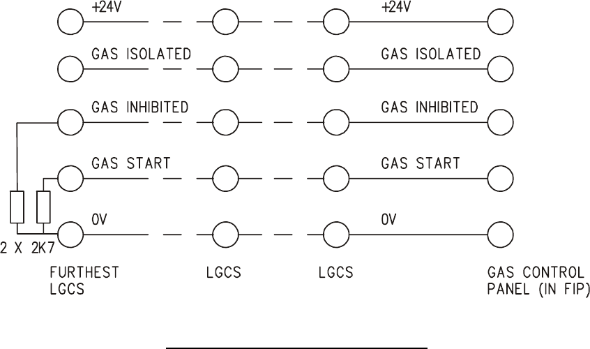
FIG 9.2.3
CONNECTION OF MULTIPLE LGCSs
9.2.6 DRAWINGS
The following drawings are included:
1931-47 1 Zone Gas Flood Door, Circuit Diagram
1937-2 Local Gas Control Station, Circuit Diagram


