


Document No: LT0122 F3200 Installation & Programming Manual
Applications
Issue 2.7 5 July 2001 Page 9-29
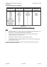
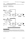
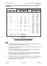
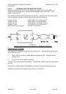
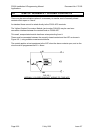
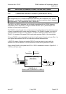
4 TERMINAL ISOLATED REPEATER WITH ZONE ADAPTOR UNIT ZAU401 (REV 2)
(CONTINUED)
GAS GROUP 11A OR 11B GAS GROUP 11C
DETECTOR
CCT LENGTH CCT LENGTH
TYPE PART BASE
QTY
1.0mm² 0.75mm²
QTY
1.00mm² 0.75mm²
SMOKE C29BEx Z94C 40(M) 3km(R) 2.2km(R) 40(M) 0.9km(C) 0.9km(C)
(100Ω)(100Ω)
(90nF) (90nF)
33 0.97km(C) 0.97km(C)
(97nF) (97nF)
20 1.1km(C) 1.1km(C)
(110nF) (110nF)
1 1.3km(C) 1.3km(C)
(130nF) (130nF)
FLAME R24BEx - 2(M) 0.5km(R) .37km(R) 2(M) 0.5km(C) 0.37km(R)
(17Ω)(17Ω)(17Ω)(17Ω )
HEAT FW105 - - - - - 1.3km TOT 1.3km TOT
(100Ω TOT) (100Ω TOT)
(130nF) (130nF)
40(M) 3km(R) 2.2km(R) 40(M) 1.3km(C) 1.3km(C)
HEAT T54B -
(100Ω)(100Ω)
(130nF) (130nF)
HEAT T56B Z500N 40(M) 3km(R) 2.2km(R) 40(M) 1.13km(C) 1.3km(C)
(100Ω)(100Ω) (130nF) (130nF)
HEAT S231i+ - 4(M) 3KM (R) 2.2KM (R) 4(M) 1.24KM(C) 1.24KM(C)
(100Ω)(100Ω) (124nF) (124nF)
1 1.28km(C) 1.28km(C)
(128nF) (128nF)
FLAME S121 - 16(M) 3km(R) 2.2km(R) 16(M) 0.66km(C) 0.66km(C)
(100Ω)(100Ω) (66nF) (66nF)
10 0.9km(C) 0.9km(C)
(90nF) (90nF)
1 126km(C) 1.26km(C)
(126nF) (126nF)
FLAME MS302Ex M300 16(M) 3km(R) 2.2km(R) 16(M) 1.06km(C) 1.06km(C)
(100Ω)(100Ω)
(106nF) (106nF)
10 1.15km(C) 1.15km(C)
(115nF) (115nF)
1 1.28km(C) 1.28km(C)
(128nF) (128nF)
ION MF301Ex M300 16(M) (SAME AS MS302Ex)
PHOTO MR301Ex M300 16(M) (SAME AS MS302Ex)
HPO MR301TEx M300 16(M) (SAME AS MS302Ex)
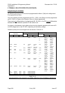
TABLE 9.4.4
MAXIMUM DETECTOR QUANTITY & CABLE LENGTH FOR
ZAU401 (REV 2) & 4-TERMINAL REPEATER
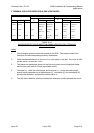
Notes
1. Circuit lengths quoted are total from the FIP to the EOL. The length quoted is the
maximum for the corresponding quantity of detectors.
2. Cable resistance shown is for the circuit, ie. both cables in the pair. The value of 34Ω
per km (return) is used for 1 mm².
3. The maximum resistances shown for the fire wire circuits must include both cable
and fire wire (see Table 9.4.2 and associated note 2).
4. The letter in ( ) after the cable length, and the value in ( ) under the cable length
specify which parameter out of capacitance (C), inductance (L) and resistance (R)
provides the limitation, and what the maximum value is.
5. The (M) after a detector quantity indicates the maximum quantity allowed per circuit.
6. The maximum allowable detector quantity corresponds to a quiescent current of
1.8mA for C29BEx, 0.3mA for R24BEx.