F3200 Installation & Programming Manual Document No: LT0122
Applications
Page 9-28 5 July 2001 Issue 2.7
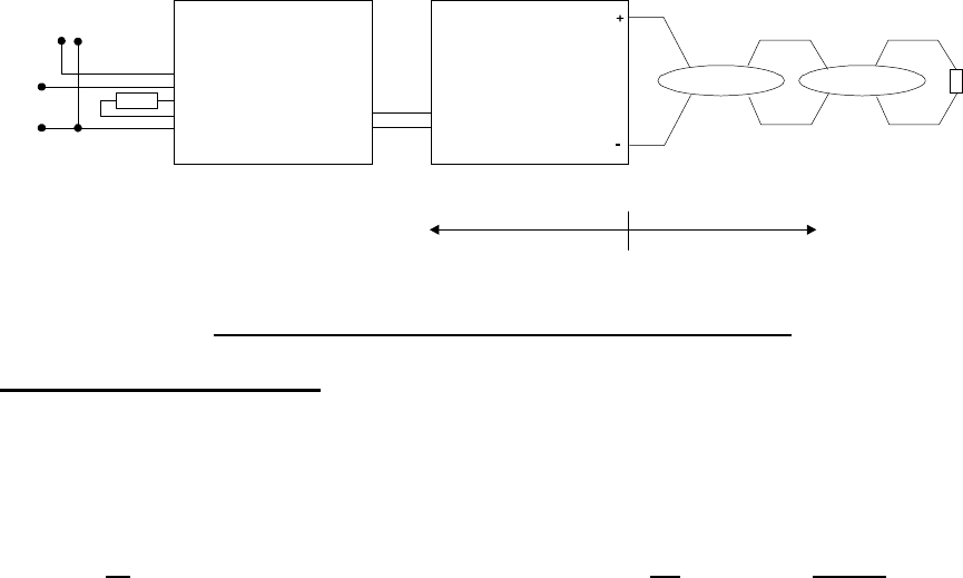
FIG 9.4.3.3
F3200 WITH ZAU401 & 4 TERMINAL IS REPEATER
Programming & Limitations
The circuit should be programmed as Mode 1 (standard). Voltage bands B1 and B3 can be
left at default, though it is better to program B1 as fault. Voltage band B3 is not generated
by a ZAU401 so can be left at the default setting (which is “normal” for V1.XX software and
“instant alarm” for V2.XX software).
Note that all alarms from the ZAU401 will give voltage band B2
i.e. the FIP cannot
differentiate between MCP and detector operation, and voltage B1 represents a short on the
circuit between the FIP and the ZAU401 (i.e. internal wiring fault).
Detector quantity and circuit length limits are shown in Table 9.4.4.
1 BATT+
2 ZONE+
3 EOL+
4 EOL-
5 ZONE-
6 BATT-
T+ 3
TC 2
T- 1
ZAU401 (Rev 2)
(PA0838)
EOL*
To Panel
Zone Circuit
+
-
+
-
Panel
24V
{
KHD0_
OR
KFD0_
OR
MTL5061
+
-
Ex DETECTOR
EOL
3k9
5%
* EOL to suit Panel
SAFE AREA HAZARDOUS AREA
4-Terminal Isolating
Repeater
Ex DETECTOR


