


F3200 Installation & Programming Manual Document No: LT0122
Installation & Wiring
Page 8-12 5 July 2001 Issue 2.7
8.4 MAF ANCILLARY RELAY WIRING
The original (AS1603.4) F3200 has a single Warning System output and Isolate Switch,
namely the Anc3/Bells relay, configured as Bells +/-, and the “Bells Isolate” key.
It is now typical for FIPs to control two outputs, i.e. a single, External Bell, and a separate
building Warning System which produces tones to AS2220 (as specified in AS4428.1).
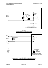
The MAF module has 3 Ancillary Relays. Typically, Anc 1 is used for door holders, air-
conditioning shutdown etc; Anc 2 is used for the External Bell; and Anc 3/Bells is used for
the Warning System. Wiring of the External Bell should be as per Fig 8.4.2 using Anc 2. The
Warning System is covered in Section 8.5. Anc 1 and Anc 2 each have 1 set of voltage free
contacts available on screw terminals, and a second set to which the screw terminals are not
fitted as standard. Where supervision of wiring is required, the supervision (SUP) input is
used as shown in the following figures.
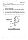
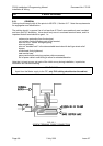
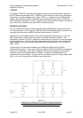
Door Holder Wiring
Door holders are typically powered through normally closed contacts from the non-battery
backed supply (+VNBF). As door holders are inductive, a suppression diode should be fitted
between 0V and the door holder positive line.
Where door holders have individual manual release buttons, suppression should be fitted at
each device.
Observe polarity,
the cathode of the suppression diode is connected to the
positive line.
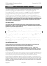
Where supervision is required, the recommended connection is as shown in Fig 8.4.1 A or B
with a return from the furthest door holder. The alternative shown in Fig 8.4.1 A does not
supervise the loop.
The 24V relay used at the end of the loop in Fig 8.4.1 B only needs to switch low current.
"Door Holder" mode supervision "looks for" the presence of voltage when the ancillary relay
is de-energised.
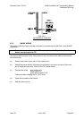
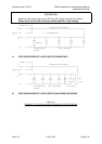
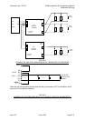
Plant Relay/Solenoid Wiring
Where a plant relay is to be energised on Ancillary Relay operation it would typically be
powered through normally open contacts from a battery-backed supply.
If wiring supervision is required, it is connected as shown in Fig 8.4.2. "Load" mode
supervision looks for a resistance to 0V when the ancillary relay is de-energised. For a very
low resistance load (ref Specifications Section 3.4.2) a series diode must be fitted as shown.
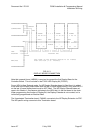
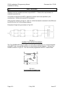
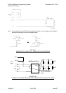
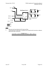
Heavy Load Wiring
If a load greater than 2A resistive (1A dc inductive) needs to be controlled by F3200 then this
can be achieved with the addition of a 24V Bell Monitor Board (PA0494). This can switch up
to 5A dc (resistive) and supervises the load wiring for open and short circuit faults.
Further details for the Bell Monitor Board are contained in LT0190. A representative wiring
diagram is shown in Figure 8.4.3. If the load exceeds 2A dc then the power connection must
be taken off +VBF2 or directly off the battery terminals via a suitable fuse (but not the +VBF1
terminal). The fuse and wiring are supervised by the Bell Monitor Board, as it will generate a
fault if power to it fails.