


F3200 Installation & Programming Manual Document No: LT0122
System Specifications
Page 3-8 5 July 2001 Issue 2.7
3.4 INPUT SPECIFICATIONS
3.4.1 AZC SPECIFICATIONS
General
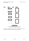
Terminations On 8 Zone Module, 2 per AZC.
Demountable screw terminal 1.5sq mm cable max.
Number 8 AZCs per 8 Zone Module.
64 max per system.
End of Lines (EOLs)
Mode EOL
1 Standard 2k7, 5%, 400mW resistor
2 High Current 2k7, 5%, 400mW resistor
3 Low Current 10k, 5%, 400mW resistor
4 Tamper EOL002B active EOL
5 Disabled None
Circuit Resistance & Capacitance
Mode Capacitance Resistance
1, 2 & 4 500nF 50 Ohm max
3 1000nF 800 Ohm max for B2 Alarm
2k Ohm max for B3 Alarm
Voltages
Min Typ Max
Detector Supply on MAF/PSU (note 1) 21.2V 22.0V 22.2V
(21.8V)
at AZC terminals 18.75V 20.3V 22.1V
at end of circuit 18.0V 20.3V 22.1V
Alarm Voltage Thresholds
Band B3 upper threshold 17.2V 17.5V 17.8V
Band B3 lower threshold 12.75V 13.1V 13.45V
Band B2 upper threshold
Band B2 lower threshold 2.7V 2.9V 3.1V
Band B1 upper threshold
Band B1 lower threshold 0V 0V 0V