


F3200 Installation & Programming Manual Document No: LT0122
Alignment, Adjustment & Placing into Operation
Page 10-2 5 July 2001 Issue 2.7
10.1 ALIGNMENT & ADJUSTMENT
All the F3200 modules (pcbs) are tested and aligned in the factory before being supplied to
the customer or fitted to a FIP. The only field adjustments that may be necessary are to set
the LCD contrast and the battery charger voltage.
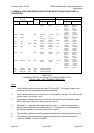
Controller/Display
VR2 LCD Contrast Adjust for best readability of the LCD when viewed from the
front of an installed FIP.
Factory adjustments include:
VR1 Set 1.2V Ref Adjust for Charger High voltage of 28.1V to 28.15V.
VR3 Adjust 15.9V Adjust until the 15.9V reference on TP15 is 15.90Vdc.
R94, Fault Threshold Snip as required to set Fault Threshold to
R105 nominal 19.03V.
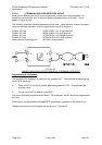
MAF/PSU
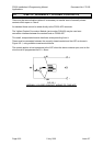
PT1 Battery Charger Voltage
Should the battery charger voltage need adjusting, the method is as follows:
1. Run the system with the door closed for at least 30 minutes to allow components to
"warm up" (the longer the better).
2. Calculate the required no-load battery charging voltage by taking 27.3V for 20°C and
subtracting approximately 0.1V for every 3°C above 20°C, or adding approximately
0.1V for every 3°C below 20°C.
3. With the system not in Alarm, disconnect the batteries.
4. Measure the voltage at the battery terminals and adjust to the voltage calculated in
Step 2 by turning PT1.
5. Re-connect the batteries.
PT2 +22V Supply is factory set and should not need field adjustment.