


Document No: LT0122 F3200 Installation & Programming Manual
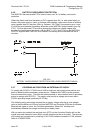
Configuring a FIP
Issue 2.7 5 July 2001 Page 5-5
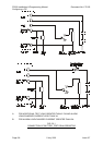
5.3.3 EXAMPLE BATTERY/CHARGER CALCULATIONS
An example FP0551 FIP has the following configuration:
3 8ZMs total (i.e. 2 x FP0553 expansion modules fitted)
1 8RM fitted
20 AZCs enabled, 4 disabled
42mA total detector current on the 20 AZCs
350mA of door holders off +VNBF
5 relays on the 8RM used, with supervision enabled, all switching 24V, 50mA relays,
normally de-energised.
Ancillary relay 1 (on the MAF) switching a 24V, 100mA load
A Bell circuit with 0.75A of 24V bell load.
Calculate the required battery capacity and check the power supply load.
Steps
1. The quiescent load (Iq) for the mains fail situation is:
130mA (FIP including one 8ZM)
+ 82mA (second 8ZM, all AZCs enabled)
+ 4mA (third 8ZM, basic current only)
+ 4 x 10mA (third 8ZM, current for 4 AZCs)
+ 42mA (detector current)
+ 6mA (8RM, supervision enabled)
304mA
Say Iq = 0.30A for mains off.
The quiescent load for mains on is Iq plus the door holders (In = 0.35A) i.e. 0.65A.
2. Say, for example, that the 2 zones in alarm can, at most, turn on 3 of the 5 module
relays plus all the bells and the Anc 1 load.
The alarm load for 2 zones in alarm is therefore:
275mA (FIP including 1 8ZM, 2 zone alarm, MAF relays)
+ 82mA (second 8ZM, quiescent only)
+ 44mA (third 8ZM, quiescent only)
+ 42mA (detector current)
+ 6mA (basic 8RM current)
+ 3 x 11mA (3 relays on 8RM)
+ 3 x 50mA (loads on 3 relays)
+ 100mA (Ancillary 1 relay load)
+ 750mA (Bells load)
1482mA
Say Ia = 1.48A (the door holders are switched off in alarm).
3. Cap (5 hr) = 5 x 0.3 + 0.66 x 1.48 Ahr = 2.49 Ahr
4. Battery charger current required is:
Ia (1.48A) is greater than Iq + In, (0.65A), therefore:
Ic = 1.48A + (2.49/24) x 1.25 = 1.61A (where the 1.25 allows for charging efficiency e
of 0.8) i.e. 3A is sufficient.
5. Battery capacity
Cap (24 hr) = [(24 x 0.3) + 0.66 x 1.48] x 1.25 = 10.2Ah.