


F3200 Installation & Programming Manual Document No: LT0122
Installation & Wiring
Page 8-24 5 July 2001 Issue 2.7
8.9 RDU WIRING
A FIP may drive up to 8 Remote Display Units (RDUs) that are programmed to send
information back to the FIP. More "monitoring only" devices may be connected to the FIP
RZDU Tx line. Some RDUs have their own power, but others require their power (24Vdc) to
be supplied from the FIP or an approved PSU with battery backup.
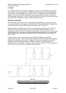
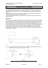
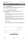
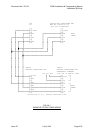
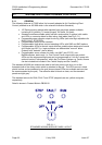
The RDUs are all connected in parallel on common Tx and Rx circuits. Star and Bus wiring
connections are permitted as shown in Fig 8.8.1.
NOTE: TX from the FIP goes to RX
on ALL RDUs
RX from the FIP goes to TX
on ALL RDUs
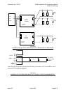
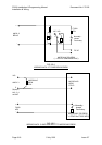
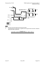
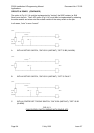
Fig 8.8.1 shows an example of interconnection between both MAF and Non-MAF configured
RDU(s) and the FIP.
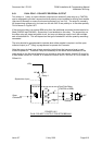
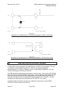
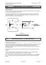
NOTES: To maintain electrical isolation:
(1) Lk1 on the MAF/PSU Board should be cut for RDUs with their own
MAF/PSU module.
(2) Non-MAF configured RDUs that are powered by a PSU other than the
FIP must have Lk3 on the Remote Termination Board cut and Lk14 on
the Controller in the “R” position.
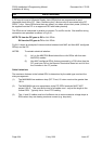
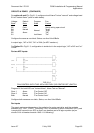
Cable Limitations
The maximum distance to the furthest RDU is determined by the cable type used and the
wiring arrangement.
(1) The MAXIMUM line resistance loop (FIP TX out, 0V return must not be greater than
150 Ω.
(2) The MAXIMUM inter-wire capacitance at the FIP RZDU terminals MUST NOT
exceed 100 nF. This must be the total of all cables used - not just the length to the
furthest RDU. Typically this is 1km of TPS cabling.
(3) The +V and 0V cables must be of sufficient size to avoid excessive voltage drops to
RDUs when they are drawing maximum current (e.g. lamp test).