F3200 Installation & Programming Manual Document No: LT0122
Applications
Page 9-12 5 July 2001 Issue 2.7
NOTES (CONTINUED)
9. If a Lock-off valve is not required, then Z7 is not required and can be left out of the
equations. Note that AS4124.1 requires the Lock-off Valve to isolate both poles of the
Gas Release solenoid / actuator. This is not done within the ME wiring and would
therefore need to be done externally with microswitches (or a relay).
10. The standard LCS Gas Start switch automatically turns on when the glass is broken.
Some customers may require a different switch that can be turned off after the glass
is broken, and hence cancel the timer and prevent gas release.
9.2.4 USE OF ACTUATORS
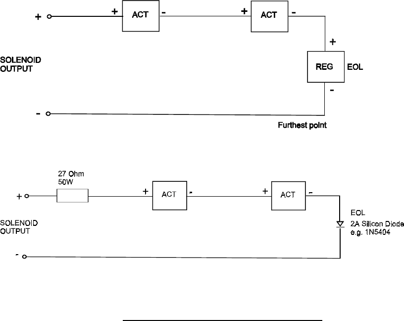
Where a CV-98 actuator is used it must be connected in series with the 427354 current
regulator, fitted at the furthest point to act as the EOL. Where series resistors have been
used (in existing circuits) to limit the current, a series diode must be fitted as the EOL. It
must be a silicon diode (not Schottky) rated at 1Adc or greater, e.g. 1N5404. See Fig 9.2.4.
A single actuator should be connected in reverse, i.e. with the black wire to the incoming
+ve voltage, so that the supervision can detect that the element has been fired.
Multiple actuators may be connected in series on one circuit, but each
must
have the red
wire to the incoming +ve voltage. Note the supervision cannot detect the difference between
an unfired element (<2 Ohm) and a fired one (3 series forward diodes).
a) With current regulator at furthest point (EOL)
b) With limiting resistor (not recommended method).
FIGURE 9.2.4
CONNECTING MULTIPLE ACTUATORS


