


Document No: LT0122 F3200 Installation & Programming Manual
Programming System Configuration
Issue 2.7 5 July 2001 Page 7-7
MODE (CONTINUED)
Switches in additional pull up resistor to +22V in Alarm.
Suits detectors with high alarm current requirement or remote LED indicators.
(Refer to Appendix A2).
Mode 3 Low Current
680 Ohm pull up resistor to +22V supply.
10k EOL.
Suits high resistance, low current circuit e.g. sub-indicator panel monitoring.
Mode 4 Tamper
680 Ohm pull up resistor to +22V supply.
Requires EOL002Z active EOL.
Suits supervision of "tamper-protected" sprinkler valves.
Mode 5 Disabled
Current limit and pull up disabled.
No EOL required.
Suits unused AZCs (saves quiescent current).
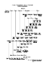
7.2.4 TIME DELAYS
The standard time delay on any change of state is 2.3 secs (2.0-2.6 secs) i.e. to Alarm, to
Fault, to Normal. During this time the input conditions are continually read (and debounced).
The input must be continuously in the new state for the duration of the time delay to cause a
change of state.
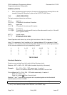
There are two programmable time delays assigned to each circuit i.e. delay into alarm Delay
1 (D1) and delay out of alarm Delay 2 (D2). One, or both of these are also used to generate
the other time delay types as follows, AVF = Alarm Verification, RAD = Return Air Detector,
SAD = Supply Air Detector.
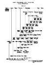
Note that the actual time delay also depends on the new condition (i.e. alarm or instant
alarm). The operation of the SAD type was changed in V2.09 software.
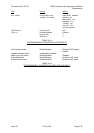
Delay Type Delay To Alarm
Delay to Normal
(applies to cct not zone)
1 Std Inst Alarm 2.3 2.3
Alarm 2.3 2.3
2 AVF/RAD Inst Alarm 2.3 2.3
Alarm (AVF/RAD sequence 2.3
using D1)
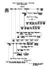
3 SAD
For V2.08 or earlier
Inst. Alarm 2.3 2.3
Alarm (AVF/RAD sequence D2
Using D1)
For V2.09 or later
Inst. Alarm 2.3 2.3
If D1 is zero (default) the into D2
Alarm time is 2.3 seconds
If D1 is non-zero the delay into
Alarm is AVF (using D1).