


F3200 Installation & Programming Manual Document No: LT0122
Installation & Wiring
Page 8-6 5 July 2001 Issue 2.7
8.1.4 LED DISPLAY INSTALLATION
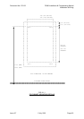
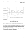
When LED Displays are required, the 7U inner door (ME0060) is fitted to the standard
cabinet directly below the 4U Operator Display with the M6 screws, washers and cage nuts
provided. The hinge is on the right hand side. Click the cage nuts in from the inside. (7U
doors cannot be fitted to a small cabinet).
The flat M6 washers have a sharp edge and a rounded edge. Fit washers to the screws with
the rounded edge facing the metalwork (to avoid damaging the paint).
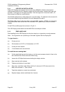
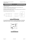
The Display Bds mount to the inner door on the standoffs supplied. (FZ3031 for LH position,
FP0475 for others, both include the PCB, standoffs, FRC, power leads, diffuser and label
master).
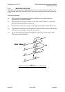
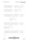
Fit the FRCs and Minijump link as shown in Fig 8.1.3.
The LED Display power leads from the MAF/PSU must always be fitted.
8.1.5 ZONE LABELLING
Zone labelling for the LED Displays can be done simply on a typewriter or word processor.
Note: For a typewriter use a photocopy of the label supplied with the Display Bd.
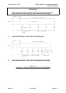
The
type format
is:
(a) 6 lines per inch.
(b) 20 characters at 10 CPI or 24 characters at 12 CPI.
(c) 2 lines per zone window.
(d) 1 line between each zone window.
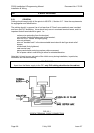
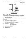
To install the zone naming label:
(a) Cut the typed label around the border, or cut the word processor sheet to 3mm to the
left of the text then 60mm wide and 220mm long.
(b) Loosen the 4 Phillips-Head screws holding the display window.
(c) Align zone text with windows.
(d) Tape top and bottom of zone label.
(e) Align clear, matt finish, light diffuser with the 3 columns of LED holes (next to the
label) with matt side in. Tape in place.
(f) Tape blank sheets to unused zone window(s).
(g) Replace display window and fasten the 4 screws.