Document No: LT0122 F3200 Installation & Programming Manual
Configuring a FIP
Issue 2.7 5 July 2001 Page 5-9
5.3.6 BATTERY OVERCURRENT PROTECTION
The MAF/PSU has two parallel PTCs, rated to carry over 3A, for battery overcurrent
protection.
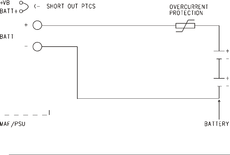
Where the Alarm load from the battery to FIP is greater than 3A (i.e. with mains failed), or
where a 6A power supply is used, an external, self-resetting, overcurrent device of suitable
rating (greater than 6A, less than 35A e.g. Derwent, 10A Type D (connected to pins 1 and
3)) must be wired between the battery terminals on the MAF/PSU and the battery (see Fig
5.3.2). For this option the PTCs must be shorted by soldering a suitable copper wire
between the two adjacent test points +VB and BATT+ (TP11 and TP16 on the MAF/PSU).
For a FIP supplied with a 6A PSU, this is done in the factory and the Derwent cut-out is
included.
FIG 5.3.2
BATTERY OVERCURRENT PROTECTION FOR LOADS GREATER THAN 3A
5.3.7 POWERING AN F3200 FROM AN EXTERNAL DC SUPPLY
To comply with AS1670.1 F3200 uses a 240Vac supply as the primary power source and
back-up batteries as the secondary power source. However the F3200 may be powered
from an external dc supply. This must be battery backed, or have another form of secondary
source to comply with AS1670.1. The supply must provide a voltage and current within
F3200’s operating range (preferably 25-27Vdc).
The following wiring instruction connects the dc supply voltage onto the ac (low voltage)
input so that the Mains on LEDs on both the MAF/PSU and Controller PCBs are illuminated.
Because this signal is not ac, the Controller generates a ‘Mains Fail’ condition and
automatically disables the charger monitoring and battery tests.
With no mains (ac) present the real time clock (RTC) on the Controller Display will use the
crystal time base instead of mains 50Hz and will therefore not be as accurate. The accuracy
of the clock can be improved by installing V3.XX F3200 software instead of V2.XX software.
Refer to LT0255/LT0256.


