


66 Hardware Switch Settings
Section 3: Installation Reference, Installation, and Operations Manual
June 2013 3-9000-743 Rev S
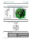
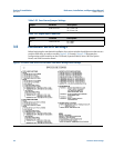
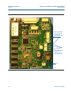
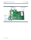
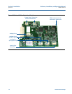
3.5 Hardware Switch Settings
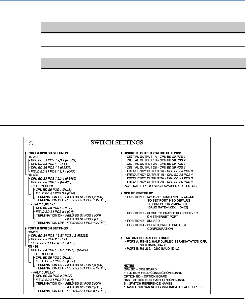
Before beginning the mechanical installation, the various switches should be set to their correct
position while they are easily accessible. Figure 3-16 through Figure 3-23 illustrates the
configuration switch locations on the CPU Board, Expansion Board, Series 100 Plus Option
Board, and Field Connection Board.
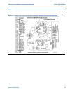
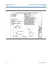
Figure 3-16 Daniel 3400 Series Gas Ultrasonic Flow Meter Wiring Switch Settings
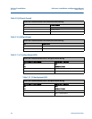
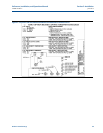
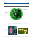
Table 3-23 Case Ground Jumper Settings
Jumper Location Description
J3 Field Conn. Bd. Pin 1 Case Gnd
Pin 2 Case Gnd
Table 3-24 Digital Input Connector
Jumper Location Description
J18 Field Conn. Bd. Pin 1 DIN+
Pin 2 DIN-