


Reference, Installation, and Operations Manual Section 2: Product overview
3-9000-743 Rev S June 2013
Status Indicators 31
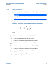
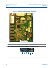
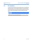
CPU Board Communication Status Indicators
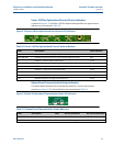
LED status indicators are provided on the CPU Board to indicate the serial Port A and B receive
and transmit statuses and to indicate the Ethernet port connection status (see Figure 2-17).
These indicators are summarized in Tab le 2 -6.
Figure 2-17 Mark III CPU Board Communication Status Indicators (I.S. Interface-Side View)
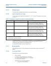
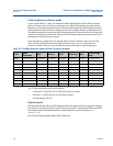
Table 2-5 CPU Board General Status Indicators
Label Description Color Indicator
LED 1 Color indicates the metrology mode Red - Acquisition Mode
Green - Measurement Mode
LED 2 Unassigned Red
LED 3 Unassigned Yellow
LED 4 Unassigned Green
LED 5 Indicates when the CPU Board is receiving
data from the
Acquisition Board
Green - Blinking when data is being received
LED 6 Unassigned Green
LED 5 is the surest indicator of the basic system health. If LED 5 is blinking, it indicates a good
connection to the Acquisition Board and the overall operation of all firmware. LED 5 should blink even if
no transducers are connected to the Acquisition Board.
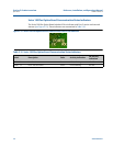
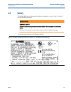
Communication Status LED Indicators