


Meter to Flow Computer Communication Worksheet 326
Reference, Installation, and Operations Manual Meter setup and configuration worksheet
3-9000-743 Rev S June 2013
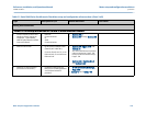
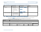
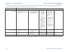
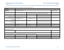
Digital Output Group 1 DO1B User Selection (Circle one) Results (Enter here)
Electrical Configuration • TTL
“Internally Powered”
• OC
“Open Collector”
Content • Flow Direction • Flow Validity
Polarity • Normal • Inverted
(see note above)
Note: Digital outputs 1A and 1B share a common ground with Frequency outputs 1A and 1B. Digital outputs 2A and 2B share a common ground with Frequency outputs 2A and 2B.
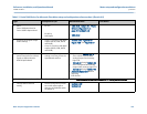
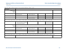
When connecting the ultrasonic meter to two different devices, it is recommended to connect Frequency outputs 1A and 1B and Digital outputs 1A and 1B to one device and
Frequency outputs 2A and 2B and Digital outputs 2A and 2B to the other device. This will prevent ground loops.
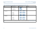
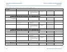
Frequency Output User Selection (Circle one) Results (Enter here)
Electrical Configuration • TTL
“Internally Powered”
• OC
“Open Collector”
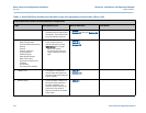
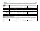
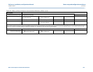
Table E-2 Meter to Flow Computer Communication Worksheet (Sheet 5 of 9)
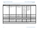
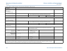
Description