


Reference, Installation, and Operations Manual Section 2: Product overview
3-9000-743 Rev S June 2013
Outputs 27
Each group has a separate ground (i.e., Group1Gnd and Group 2 Gnd) and there is up to 50 V
isolation between the two groups. Thus, all outputs within a group share a common ground.
This allows each output group to be connected to a different flow computer. Daniel should be
consulted before establishing the actual meter capacity for a particular application.
All outputs are opto-isolated from the CPU Board (with a withstand of at least 500 Volt rms
dielectric).
Each output is individually configurable as either internally powered (TTL) or externally powered
(“open collector” e.g. O.C.). An output signal configured as “internally powered” is powered
from an internal isolated 5 VDC bus and has voltage levels and drive capability as shown in
Tab le 2 -3.
An output signal configured as “open collector” (externally powered) must not exceed 60 VDC
and must not be allowed to sink more than 50 mA.
Cable length TTL mode
The maximum cable length is 2000 feet when the “TTL” mode is selected.
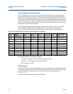
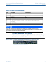
Table 2-3 Voltage level and drive capability per logic level (TTL)
Logic Value Voltage Level Drive Capability
0 < 0.7 V maximum sinking current:10 mA
1 > 3.5 V maximum sourcing current:10 mA
If outputs from both groups are to be connected to the same device, then the two group
grounds must be connected together, either at the Daniel Mark III Ultrasonic Gas Flow Meter
Field Connection Board or at the flow computer, whichever is more convenient.