


Reference, Installation, and Operations Manual Section 7: Maintenance and troubleshooting
3-9000-743 Rev S June 2013
Modifying the Calibration Parameters 271
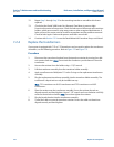
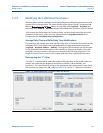
7.2.5 Modifying the Calibration Parameters
When transducer pairs are replaced, the corresponding meter calibration parameters must be
updated for accurate operation. This means modifying the affected chord "L" dimension (LA ...
LD) (see Determining the “L” Value below), average delay time (AvgDlyA ... AvgDlyD) and
delta delay time (DltDlyA ... DltDlyD) using the Daniel MeterLink Transducer Swap-out Wizard.
After running the Daniel MeterLink Transducer Swap- out Wizard and writing the new chord
parameters to the meter, collect and save a Maintenance log (
Logs/Reports menu) and a
Configuration file (
Tools>Edit/Compare Configuration).
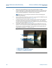
Average Delay Time and Delta Delay Time Modifications
The transducer pair average delay time and delta delay time are located on the transducer pair
calibration sheet. These values must be downloaded to the appropriate meter data points
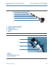
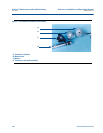
(AvgDlyA ... AvgDlyD, DltDlyA ... DltDlyD). The lengths of the transducers are also included
on the calibration sheet and are etched on the transducers. Likewise the lengths of the stalk
assemblies, transducer holders, and mounts are etched on the individual components. The
length of the meter body is found on the original calibration sheet supplied with the meter.
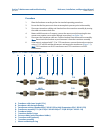
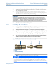
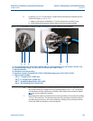
Determining the “L” Value
The value “L” is determined by adding the length of the meter body to the lengths of the two
mounts and subtracting the lengths of the transducer holders, stalk assemblies, and
transducers. This value should be written to the appropriate meter data points for each chord
that received new transducers (LA ...LD). See Equation B-5 for the “L” dimension calculation.
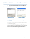
Figure 7-9 Daniel MeterLink Transducer Swap-out Wizard